Design and function
MIG/MAG welding
28
099-005445-EW501
22.9.2022
• Insert the central plug for the welding torch into the central connector and screw together with crown
nut.
• Insert the plug on the workpiece lead into the "-" welding current connection socket and lock.
• Insert the polarity selection plug into the "+" welding current connection socket and lock in place by
turning to the right.
Where applicable:
• Insert the welding torch control cable into the 19-pole connection socket and lock (MIG/MAG torches
with additional control cables only).
• Lock connecting nipples of the cooling water tubes into the corresponding quick connect couplings:
Return line red to quick connect coupling, red (coolant return) and
supply line blue to quick connect coupling, blue (coolant supply).
5.2.2 Wire feed
CAUTION
Risk of injury due to moving parts!
The wire feeders are equipped with moving parts, which can trap hands, hair, clothing
or tools and thus injure persons!
• Do not reach into rotating or moving parts or drive components!
• Keep casing covers or protective caps closed during operation!
Risk of injury due to welding wire escaping in an unpredictable manner!
Welding wire can be conveyed at very high speeds and, if conveyed incorrectly, may es-
cape in an uncontrolled manner and injure persons!
• Before mains connection, set up the complete wire guide system from the wire spool to the
welding torch!
• Check wire guide at regular intervals!
• Keep all casing covers or protective caps closed during operation!
5.2.2.1 Inserting the wire spool
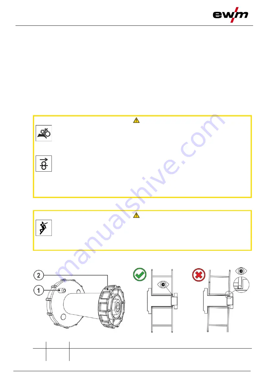
CAUTION
Risk of injury due to incorrectly secured wire spool.
If the wire spool is not secured properly, it may come loose from the wire spool support
and fall to the ground, causing damage to the machine and injuries.
• Make sure to correctly fasten the wire spool to the wire spool support.
• Before you start working, always check the wire spool is securely fastened.
Standard D300 wire spool holder can be used. Adapters are required when using standardised
basket coils (DIN 8559)
> see 9 chapter
.
Figure 5-11
Item Symbol Description
0
1
Carrier pin
For fixing the wire spool


