Design and function
Transport and installation
099-005592-EW501
16.07.2018
17
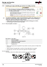
Figure 5-5
Item Symbol
Description
0
1
G¼" connecting nipple, shielding gas connection
2
7-pole connection socket (digital)
• Control lead for wire feed unit
3
Quick connect coupling (red)
Coolant return
4
Quick connect coupling (blue)
Coolant feed
5
Power source welding current connector plug
Welding current connection between power source and wire feeder
6
Strain relief
7
Safety belt
Intermediate hose package strain relief
8
Intermediate hose package
9
Power source
• Insert the hose package end through the intermediate hose package strain relief and secure with the
safety belt as shown in the figure.
• Push the welding current cable socket onto the “welding current connecting plug” and lock by turning
to the right.
• Connect crown nut of the shielding gas line to the G¼“ connecting nipple.
• Insert cable plug on the control lead into the 7-pole connection socket and secure with crown nut (the
plug can only be inserted into the connection socket in one position).
• Lock connecting nipples of the cooling water tubes into the corresponding quick connect couplings:
Return line red to quick connect coupling, red (coolant return) and
supply line blue to quick connect coupling, blue (coolant supply).


