background image


Design and function 

MMA welding or gouging 


099-005592-EW501 

16.07.2018


25


5.3 

MMA welding or gouging 

For connection descripti

on, see the relevant “Power source” operating instructions. 

5.3.1 

Welding task selection 

For selection of the welding task and for general operation see the relevant Control operating instructions. 

5.4 

Remote control


The manufacturer's warranty becomes void if non-genuine parts are used! 
•  Only use system components and options (power sources, welding torches, electrode 

holders, remote controls, spare parts and replacement parts, etc.) from our range of products! 

•  Only insert and lock accessory components into the relevant connection socket when the 

machine is switched off. 


Remote controls are used for the remote operation of various machine functions (see operating 
instructions for remote control). Depending on the machine design, the remote control connection can be 
7- or 19-pole (connection see chapter Machine description

 > see 4 chapter

). 


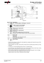
Figure 5-16 


Item  Symbol 

Description

 0


Remote control 


•  Insert the remote control connector plug into the wire feeder remote control connection (19-pole) and 

lock by turning to the right. 


Summary of Contents for Drive 4 Basic S D200

Page 1: ...Operating instructions EN Wire feed unit Drive 4 Basic S D200 Drive 4X Steel Synergic S D200 Drive 4X Steel puls S D200 099 005592 EW501 Observe additional system documents 16 07 2018...

Page 2: ...uthorised sales partners can be found at www ewm group com en specialist dealers Liability relating to the operation of this equipment is restricted solely to the function of the equipment No other fo...

Page 3: ...stallation of welding current leads 15 5 1 4 Stray welding currents 16 5 1 5 Intermediate hose package connection 16 5 1 6 Shielding gas supply shielding gas cylinder for welding machine 18 5 1 6 1 Pr...

Page 4: ...chnical data 32 8 1 Drive 4 D200 32 9 Accessories 33 9 1 General accessories 33 9 2 Remote control connecting and extension cable 33 10 Replaceable parts 34 10 1 Wire feed rollers 34 10 1 1 Wire feed...

Page 5: ...Contents Notes on the use of these operating instructions 099 005592 EW501 16 07 2018 5...

Page 6: ...ng or operating procedures which must be closely observed to prevent possible minor personal injury The safety information includes the CAUTION keyword in its heading with a general warning symbol The...

Page 7: ...n These operating instructions are part of the complete documentation and valid only in combination with all other parts of these instructions Read and observe the operating instructions for all syste...

Page 8: ...in line with its designated purpose and by trained or expert personnel Do not improperly modify or convert the equipment 3 1 Applications MMA welding system for GMAW pulse and standard welding as a M...

Page 9: ...horised by the manufacturer this declaration shall be voided An original document of the specific declaration of conformity is included with every product 3 3 3 Service documents spare parts and circu...

Page 10: ...Front view side view from left Figure 4 1 Item Symbol Description 0 1 Carrying handle 2 Welding torch connection Euro or Dinse torch connector Welding current shielding gas and torch trigger integrate...

Page 11: ...ching of the wire electrode through the hose package to the welding torch see 5 2 3 4 chapter 12 Sticker JOB List 13 Gas flow controller Fine adjustment of gas flow 14 19 pole connection socket analog...

Page 12: ...train relief see 5 1 5 chapter 3 Wheels 4 Rotary closure Locking of the protective cap 5 Protective cap 6 Power source welding current connector plug Welding current connection between power source an...

Page 13: ...Do not lift or suspend the machine The machine can drop and cause injuries The handles straps or brackets are suitable for transport by hand only The machine must not be suspended or lifted using a cr...

Page 14: ...ts When changing the coolant the entire volume of liquid must be changed Dispose of the coolant in accordance with local regulations and the material safety data sheets 5 1 2 1 Approved coolants overv...

Page 15: ...with HF igniter TIG for as long as possible in parallel with a distance of 20 cm to avoid HF sparkover Always keep a distance of at least 20 cm to leads of other power sources to avoid interferences A...

Page 16: ...up attach or suspend all conductive power source components such as casing transport vehicles and crane frames so they are insulated Do not place any other electronic devices such as drills or angle g...

Page 17: ...ower source Insert the hose package end through the intermediate hose package strain relief and secure with the safety belt as shown in the figure Push the welding current cable socket onto the weldin...

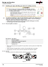
Page 18: ...is a fundamental requirement for optimum welding results In addition a blocked shielding gas supply may result in the welding torch being destroyed Always re fit the yellow protective cap when not us...

Page 19: ...a guide tube Operate welding torches with a steel liner with a capillary tube Depending on the wire electrode diameter or type either a steel liner or liner with the correct inner diameter must be in...

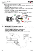
Page 20: ...before the wire feed roller Loosen the welding torch connector and remove Carefully chamfer the cut off end of the liner with a liner sharpener see 9 chapter and sharpen Figure 5 10 5 2 2 Welding tor...

Page 21: ...equipped with moving parts which can trap hands hair clothing or tools and thus injure persons Do not reach into rotating or moving parts or drive components Keep casing covers or protective caps clos...

Page 22: ...heck the roller label to verify that the rollers are suitable for the wire diameter Turn or change if necessary use V groove rollers with for steel wires and other hard wires use U groove rollers for...

Page 23: ...m Symbol Description 0 1 Adjusting nut 2 Feed roll tensioner Fixing the clamping unit and setting the pressure 3 Clamping unit 4 Knurled screw 5 Drive roller 6 Guide tube 7 Wire feed nipple 8 Pressure...

Page 24: ...NING Do not carry out any unauthorised repairs or modifications To avoid injury and equipment damage the unit must only be repaired or modified by specialist skilled persons The warranty becomes null...

Page 25: ...g torches electrode holders remote controls spare parts and replacement parts etc from our range of products Only insert and lock accessory components into the relevant connection socket when the mach...

Page 26: ...ight to claim under warranty is void In all service matters always consult the dealer who supplied the machine Return deliveries of defective equipment subject to warranty may only be made through you...

Page 27: ...ly tighten if necessary Remove any spatter Clean the wire feed rollers on a regular basis depending on the degree of soiling 6 3 2 Monthly maintenance tasks Visual inspection Casing damage front rear...

Page 28: ...r on wheels indicates that the equipment must be collected separately This machine has to be disposed of or recycled in accordance with the waste separation systems in use According to German law law...

Page 29: ...lant pump Check air cooling unit overcurrent trip 5 x Wire feeder tachometer error Check the wire feeder Tachogenerator is not emitting a signal M3 51 defective inform Service 6 x Shielding gas error...

Page 30: ...d process gas in use is a fundamental requirement for perfect operation Legend Symbol Description Fault Cause Remedy Coolant error no coolant flowing Insufficient coolant flow Check coolant level and...

Page 31: ...minated after switching on No welding power Phase failure check mains connection fuses Several parameters cannot be set machines with access block Entry level is blocked disable access lock Connection...

Page 32: ...roll equipment 1 0 1 2 mm for steel wire Drive 4 rollers 37 mm Wire spool diameter Standardised wire spools up to 200 mm Welding torch connection Euro torch connector Protection classification IP 23...

Page 33: ...Item no DM 842 Ar CO2 230bar 30l D Pressure regulator with manometer 394 002910 00030 AK300 Wire spool adapter K300 094 001803 00001 HOSE BRIDGE UNI Tube bridge 092 007843 00000 SPL Sharpener for lin...

Page 34: ...0 1 2 Drive rollers 37 mm steel 092 000842 00000 FE 2DR4R 1 2 1 6 Drive rollers 37 mm steel 092 000843 00000 FE AL 2GR4R SF Pressure rollers smooth 37 mm 092 000414 00000 10 1 2 Wire feed rollers for...

Page 35: ...or cored wire 092 000411 00000 URUE ROE 2DR4R 1 4 1 6 2 0 2 4 SF Conversion kit 37 mm 4 roller drive for cored wire 092 000412 00000 URUE ROE 2DR4R 2 8 3 2 SF Conversion kit 37 mm 4 roller drive for c...

Page 36: ...x A Searching for a dealer 36 099 005592 EW501 16 07 2018 11 Appendix A 11 1 Searching for a dealer Sales service parteners www ewm group com en specialist dealers More than 400 EWM sales partners wor...

Reviews: