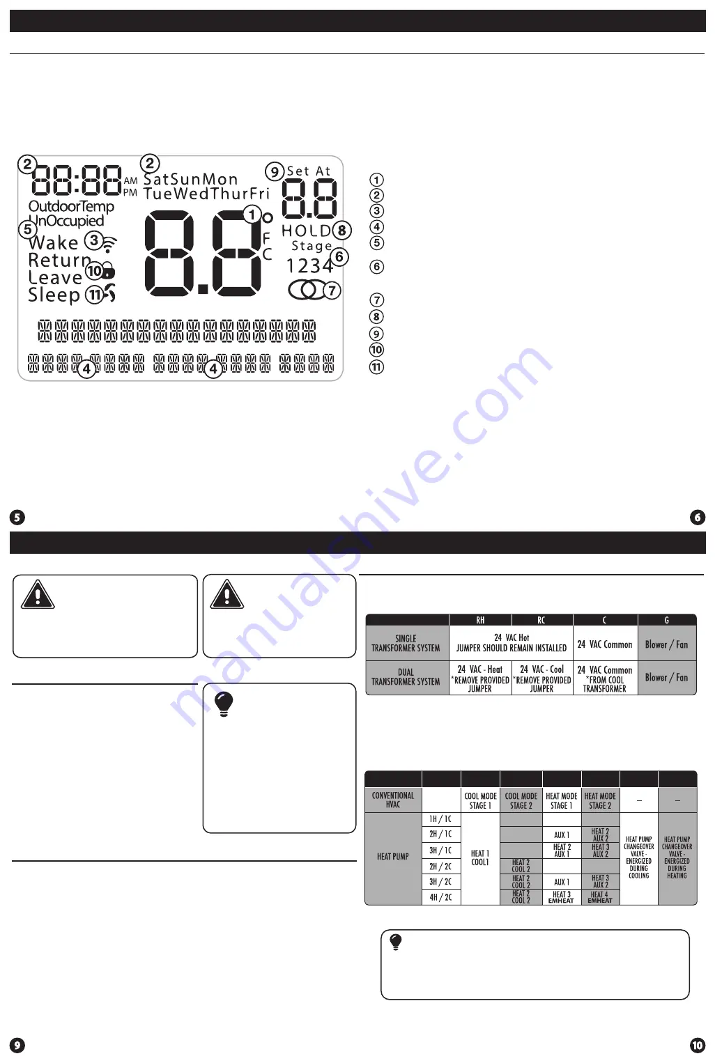
Wiring Chart
For all systems, the following terminals are wired according to whether you
have a single or dual transformer system as shown:
Wiring
Wiring
Caution:
Electrical Hazard
All components of the control
system and the thermostat
installation must conform to
Class II circuits per the NEC Code.
Warning:
Do not overtighten terminal
block screws, as this can
damage the terminal block.
A damaged terminal block
can keep the thermostat
from fitting on the subbase
correctly or cause system
operation issues.
Installation Tip
Max Torque = 6in-lbs.
Wiring
If you are replacing a thermostat,
make note of the terminal
connections on the thermostat that
is being replaced. In some cases
the wiring connections will not be
color coded. For example, the
green wire may not be connected
to the
G
terminal.
Loosen the terminal block screws.
Insert wires then retighten the
terminal block screws.
Place nonflammable insulation into
the wall opening to prevent drafts.
1.
2.
3.
Wiring Tips
C Terminal
This thermostat requires a 24V
common wire to the C terminal.
Wire Specifications
Use shielded or non-shielded 18-22
gauge thermostat wire.
Failure to disconnect the power
before beginning to install this
product can cause electrical shock
or equipment damage.
Note:
In many heat pump systems with
no emergency heat relay, a jumper
can be installed between
E
and
W2
to turn thermostat into a single
stage control for Emergency Heat
Operation.
Thermostat Quick Reference
Indicates the current room temperature
Time and day of the week
Staging Indicators:
Indicates stages of heat or cool running. The compres-
sor delay feature is active if these are flashing.
Setpoint:
Displays the user selectable setpoint temperature.
Hold:
Is displayed when the thermostat program is permanently overridden.
WIFI Connection Indicator
WIFI Signal Strength
Button Options
Program Time Periods - Residential:
Uses 4 time periods - WAKE, RETURN,
LEAVE & SLEEP. Commercial uses 2 time periods - OCCUPIED, UNOCCUPIED.
Getting to know your thermostat
Thermostat Quick Reference
Lockout Indicator
Fan Indicator
FAILURE TO REMOVE PROVIDED JUMPER ON DUAL TRANSFORMER INSTALLATIONS
COULD CAUSE SEVER DAMAGE TO HVAC SYSTEMS
The following terminals on the thermostat wallplate are wired
according to the type of HVAC system connected to and how the
thermostat is configured.
Devices such as a float switch that mechanically break circuits should
be installed so that they break the control wire (Y) not the power (R).
Interrupting the power circuit will shut off power to the thermostat
completely and not allow it to operate.
Note
Y1 Y2 W/E W2 O B
Getting to know your thermostat


