background image

Contetns


eLR100-UL-00 Manual for Consumer Products, Rev. 0.2, 02/2020                      

2 | 24


CONTETNS 

Contetns .............................................................................................................................................................................................. 2


1.


Introduction ............................................................................................................................................................................ 3


1.1.


Features .............................................................................................................................................................................. 3


1.2.


Block Diagram ..................................................................................................................................................................... 4


2.


Functional Description ............................................................................................................................................................ 5


2.1.


Part Description .................................................................................................................................................................. 5


2.2.


Power .................................................................................................................................................................................. 6


2.3.


Reset ................................................................................................................................................................................... 7


2.4.


Arduino Type Header Grove connector .............................................................................................................................. 8


3.


Application ............................................................................................................................................................................ 10


3.1.


Firmware Upload .............................................................................................................................................................. 10


3.2.


Arduino Example ............................................................................................................................................................... 12


3.3.


LORA Behavior Example (LoRaCommunication.ino) ......................................................................................................... 14


4.


Host Device Application ........................................................................................................................................................ 15


4.1.


Circuit ................................................................................................................................................................................ 15


4.2.


Module Mechanical Dimension ........................................................................................................................................ 16


4.3.


antenna ............................................................................................................................................................................. 17


Document Revision and Reference

 .............................................................................................................................................. 21


Summary of Contents for eLR100-UL-00

Page 1: ...eLR100 UL 00 Manual FCC ID 2ARG9 ELR100 IC 2891 ELR100 eWBM LoRa Module eLR100 UL 00 Powered by MS500 ...

Page 2: ...tional Description 5 2 1 Part Description 5 2 2 Power 6 2 3 Reset 7 2 4 Arduino Type Header Grove connector 8 3 Application 10 3 1 Firmware Upload 10 3 2 Arduino Example 12 3 3 LORA Behavior Example LoRaCommunication ino 14 4 Host Device Application 15 4 1 Circuit 15 4 2 Module Mechanical Dimension 16 4 3 antenna 17 Document Revision and Reference 21 ...

Page 3: ...rs for use by connecting to the Arduino board and Shield Type 1 1 FEATURES eLR100 UL 00 Module include eWBM ultra low power advanced security MCU MS500 Cortex M0 Hardware Security system Semtech SX1276 radio transceiver supporting LoRa High sensitivity down to 135 5 dBm 902 3MHz to 914 9 MHz 125 kHz 903 0MHz to 914 2 MHz 500 kHz Max 14 dBM Output Power LoRa Alliance Certified UART Communication In...

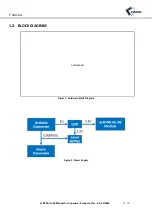
Page 4: ...Contetns eLR100 UL 00 Manual for Consumer Products Rev 0 2 02 2020 4 24 1 2 BLOCK DIAGRAM Figure 1 Hardware Block Diagram Figure 2 Power Supply Confidential ...

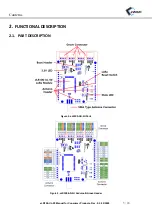
Page 5: ...Contetns eLR100 UL 00 Manual for Consumer Products Rev 0 2 02 2020 5 24 2 FUNCTIONAL DESCRIPTION 2 1 PART DESCRIPTION Figure 3 eLR100 AD SU Parts Figure 4 eLR100 AD SU Arduino Grove Header ...

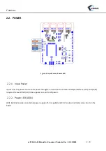
Page 6: ...put Power Inputs from the power source enter power through Pin 5 and 6 in the Arduino Headpin Interface JA1 Pin 2 IREF requires the Level Shift U3 to be supplied as a pin for V5 power 2 2 2 Power LED LED1 LED1 illuminates when an external power supply of 5V is applied and 3 3V is output normally via a circuit on the board ...

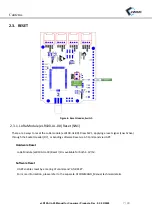
Page 7: ...e LoRa module eLR100 UL 00 Rress SW1 applying a reset signal Low Active through the Socket Header D7 or Sending software Reset via AT Command via UART Hardware Reset LoRa Module eLR100 UL 00 Reset I O is available for both 3 3V 5V Software Reset UART enables reset by entering AT Command AT RESET For more information please refer to the separate ATCOMMAND_Manual technical details ...

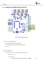
Page 8: ...HEADER GROVE CONNECTOR Figure 7 Arduino Type Header Description 2 4 1 D2 D3 UART out in Header communicating with Arduino UNO AT COMMAND Debug Firmware Update are all possble 5V I O 2 4 2 D4 State Out Header pin to check the status of LoRa Module eLR100 UL 00 Normal Mode HIGH Sleep Mode LOW ...

Page 9: ... Mode OFF 2 4 3 D7 LoRa Reset IN Connected to the Reset of the LoRa Module eLR100 UL 00 The PNP TR is connected inside the eLR100 AD SU which allows control of all 3 3V 5V 2 4 4 Grove Connector The A0 A1 D8 D9 SCL and SDA signal lines are not connected to the LoRa Module eLR100 UL 00 but directly to the Grove Connector in the Arduino Header ...

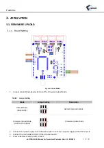
Page 10: ...o set the Firmware Upload Mode Table 1 Jumper Setting Mode Jumper Setting Description Default Mode ROM BOOT Normal Operation Mode Firmware Upload Mode UART to Flash Boot Firmware Update Mode 2 Connect a 5V power supply to the Arduino Header Connect a 5V power supply to the IOFF as well 3 Connect the Uart cable to D0 D1 of the Arduino Header 4 Press LoRa Reset Switch SW1 to reset ...

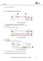
Page 11: ...to your PC click Scan 2 Set COM Port to the port to which the eLR100 AD SU is connected 3 Select QSPI 4 Click to select the img file to upload Figure 10 Firmware Setting 2 5 Click Connect 6 Click Upload 7 Check the Upload status through the green bar Figure 11 Firmware Setting 3 8 Firmware Upload Success Confirm the message and click it After upload return the Board settings to their default value...

Page 12: ...om 3 2 1 Installing the Arduino Library Importing Run Arduino IDE From the menu access and select Sketch Include Library Add ZIP Library Select a deployed ZIP file For more information see Link below https www arduino cc en Guide Libraries toc4 3 2 2 Running the Arduino Example After running the Arduino IDE access and select Tools ard Board Arduino UNO order from the menu Select File Extensions eW...

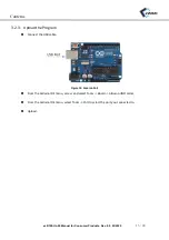
Page 13: ...Rev 0 2 02 2020 13 24 3 2 3 Upload the Program Connect the USB cable Figure 12 Arduino Port From the Arduino IDE menu access and select Tools Board Arduino UNO order From the Arduino IDE menu select Tools Port to select the port you connected to Upload ...

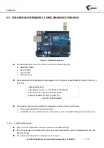
Page 14: ...t LoRa Module Version 1 1 15 e07713e Darthvader LoRa Device EUI 02 02 02 02 02 02 02 02 Select Lora Mode OTAA 1 or ABP 2 Figure 14 LoRa Command LoRa motion mode must be selected and operated in either OTAA or ABP mode Choose according to the purpose and join LoRaWAN For more information on LoRa please refer to the LoRaWAN Specification document 3 3 1 LoRa Preferences Refer to the AT COMMAND comman...

Page 15: ...Contetns eLR100 UL 00 Manual for Consumer Products Rev 0 2 02 2020 15 24 4 HOST DEVICE APPLICATION 4 1 CIRCUIT VCC_3 3V VDD_RFS Voltage Range 3 0V to 3 6V Figure 14 Application Circuit Confidential ...

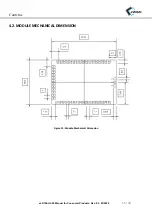
Page 16: ...Contetns eLR100 UL 00 Manual for Consumer Products Rev 0 2 02 2020 16 24 4 2 MODULE MECHANICAL DIMENSION Figure 15 Module Mechanical Dimension ...

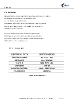
Page 17: ...ne tuning of return loss etc can be performed using a matching network However it is required to check Class1 change and Class2 change which the authorities define then The concrete contents of a check are the following three points 1 It is the same type as the antenna type of antenna specifications 2 An antenna gain is lower than a gain given in antenna specifications 3 The emission level is not ...

Page 18: ...ide of Figure where components C6 C7 are not installed they were options on the reference board for future uses these uses are not FCC authorized yet As preliminary information the traces width of all sections are all 0 5mm and the length of eLR100 UL 00 pad to J2 connector are 6 2mm However refer to associated Gerber files for more details on dimensions and refer to EWBM Inc for more details on t...

Page 19: ... 00 Manual for Consumer Products Rev 0 2 02 2020 19 24 4 3 3 PCB Stack Up and Trace PCB Stack up for the reference board Figure 18 PCB Stack Up Below figure 18 shows the Top layer routing of the complete reference board ...

Page 20: ...gn verification stage and in production for ensuring compliance 1 Initiate Continuous Transmission in the appropriate modulation mode from the device i e 902 3MHz 908 7MHz 914 9MHz FHSS mode and 903MHz 907 8MHz 914 2MHz DTS mode 2 Verify RF power through conducted measurement at junction J2 3 The measured Tx power should be within the datasheet specification for Transmit output power ...

Page 21: ...vision and Reference eLR100 UL 00 Manual for Consumer Products Rev 0 2 02 2020 21 24 DOCUMENT REVISION AND REFERENCE Revision History Revision Date Description 0 1 2019 12 10 1st Release 0 2 2020 02 10 2st Release ...

Page 22: ... means electronic mechanical manual optical or otherwise without prior written permission of eWBM Co Ltd NO WARRANTY NOTICE eWBM Co Ltd makes no warranty of any kind in regard to this material which is delivered to you as is including but not limited to the implied warranties as to its accuracy or fitness for a specific purpose Any use of this technical documentation or the information contained t...

Page 23: ...which the receiver is connected Any changes or modifications not expressly approved by the party responsible for compliance could void the user s authority to operate this equipment The antenna s must be installed such that a minimum separation distance of at least 20 cm is maintained between the radiator antenna and all persons at all times IC Statement This device complies with Industry Canada l...

Page 24: ...nsmitter except in accordance with FCC multi transmitter product procedures The OEM integrator will be responsible to satisfy SAR RF Exposure requirements when the module integrated into the host device The module is labeled with its own FCC ID and IC certification If the FCC ID and IC Certification Number are not visible when the module is installed inside another device then the outside of the d...

Reviews: