EVS SYNAPSE CDV29 Installation And Configuration Manual Download Page 8

INSTALLATION AND CONFIGURATION MANUAL 

CDV29 


3  A Quick Start 

When Powering-up 

On powering up the Synapse frame, the card set will receive basic 
data and default initialisation settings. All LEDs will light during 
this process. After initialisation, several LEDs will remain lit – the 
exact number and configuration is dependant upon the number of 
inputs connected and the status of the inputs.  


Default settings 

In its default condition, the CDV29 will act as a Reference 
distribution amplifier.  


Changing 

parameters and 

settings 

The front panel controls or the Synapse Cortex Software can be 
used to change settings. An overview of the settings can be found 
in chapter 5, 6 and 7 of this manual. 


Front Panel Control 

Front Panel Display and Cursor 


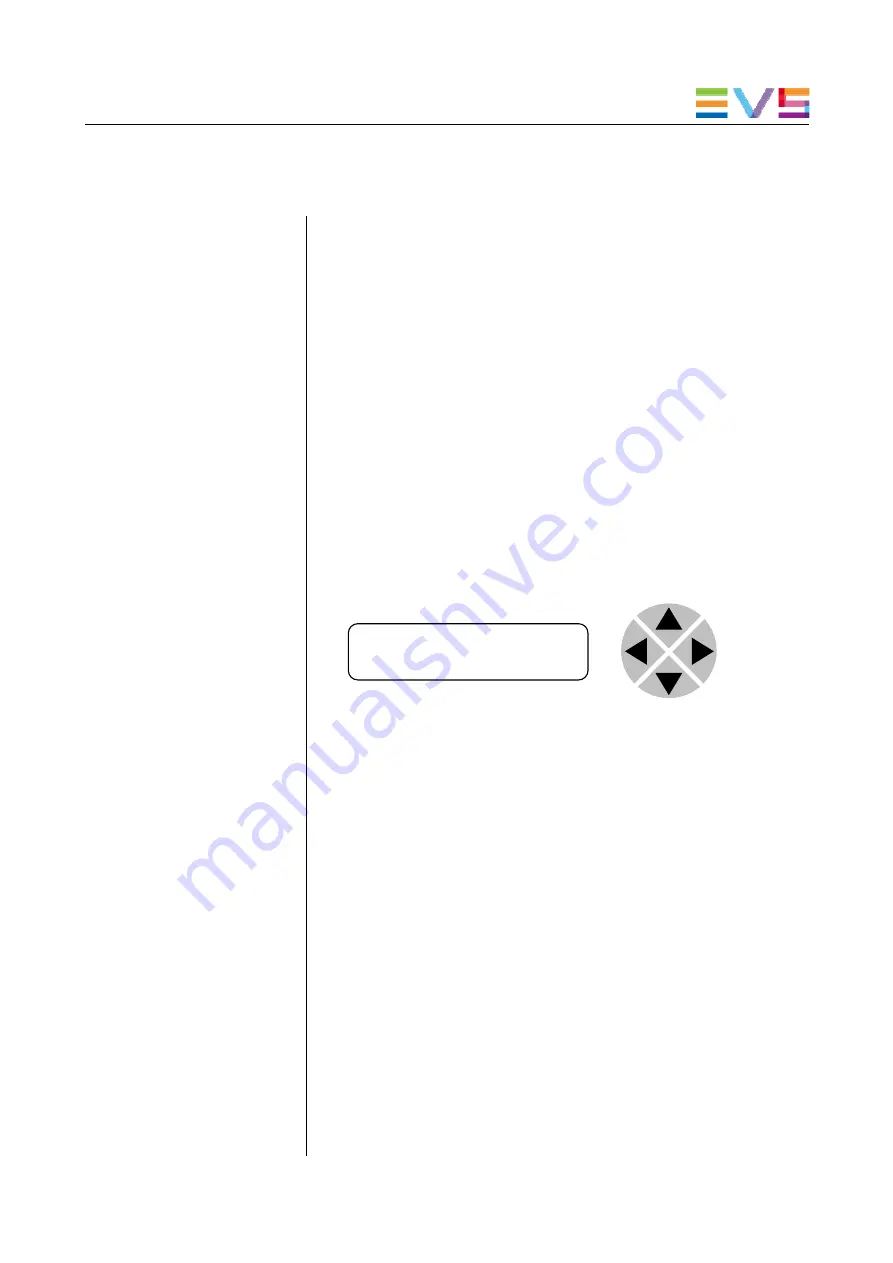
Settings are displayed and changed as follows; 
 
Use the cursor ‘arrows’ on the front panel to select the menu and 
parameter to be displayed and/or changed. 
 

Press 

 To 

go forward through the menu structure. 

Press 

 To 

go back through the menu structure. 

Press 


To move up within a menu or increase the value of 
a parameter. 

Press 


To move down through a menu or decrease the 
value of a parameter. 


REMARK:

 Whilst editing a setting, pressing 

 twice will reset 

the value to its default. 


[No Alarms] 

Summary of Contents for SYNAPSE CDV29

Page 1: ...INSTALLATION AND CONFIGURATION MANUAL CDV29 REFERENCE DISTRIBUTION AMPLIFIER S...

Page 2: ...e user documentation Do not hesitate to send improvement requests or report any error or inaccuracy on this user manual by e mail to doc evs com Regional Contacts The address and phone number of the E...

Page 3: ...duct to extremely high or low temperatures NEVER operate this product in an explosive atmosphere Warranty EVS warrants their products according to the warranty policy as described in the general terms...

Page 4: ...efault settings 6 Changing parameters and settings 6 Front Panel Control 6 Example of changing parameters using front panel control 7 Synapse Cortex Software 8 Menu Structure Example 8 The CDV29 Card...

Page 5: ...12 Analog_Inp1 12 Analog_Inp2 12 What information is available in an event 12 The Message String 12 The Tag 13 Defining Tags 13 The Priority 13 The Address 13 LED Indication 14 POWER LED 14 INPUT LED...

Page 6: ...Synapse rack controller The local control panel is also used to back up and restore card settings Please refer to the RRC18 RRC10 RRC04 RRS4 RRS18 manuals for a detailed description of the local cont...

Page 7: ...d will prevent premature failure from components mounted on the board Locating the card The Synapse card can be placed vertically in an SFR18 frame or horizontally in an SFR04 frame Locate the two gui...

Page 8: ...rs and settings The front panel controls or the Synapse Cortex Software can be used to change settings An overview of the settings can be found in chapter 5 6 and 7 of this manual Front Panel Control...

Page 9: ...play changes to indicate that the SFS10 Settings menu item SDI Format has been selected and shows that it current setting is Auto Pressing the selects the settings item shown in this example SDI Forma...

Page 10: ...he Cortex software has access to data contained within the Synapse module and displays it on a GUI The software has an intuitive structure following that of the module that it is controlling A descrip...

Page 11: ...ed input Back planes The CDV29 can be used with a BPL01 back plane If the BPL01 is used then the CDV29 have nine outputs Miscellaneous The CDV29 cards fit into the EVS SFR18 or SFR04 rack LEDs at the...

Page 12: ...an SFR04 The option Auto makes the input selection automatically with Ref1 as priority so when there is a reference on both inputs Ref1 will be selected Whenever Ref1 is lost Ref2 is automatically sel...

Page 13: ...there is a signal present or not NA on reference input 1 Analog Inp2 This status item displays if there is a signal present or not NA on reference input 2 Active Inp This status item displays the cur...

Page 14: ...0 off other on Analog_Inp1 Analog_Inp1 can be selected between 0 255 0 no event 1 255 is the priority setting Analog_Inp2 Analog_Inp2 can be selected between 0 255 0 no event 1 255 is the priority se...

Page 15: ...ning Tags The tags defined are Event Menu Item Tag Description Announcements 0 or NA 0 or NA Announcing of report and control values Input 01hex INP_LOSS 81hex INP_RETURN primary input lost or returne...

Page 16: ...ication POWER LED The power LED indicates the presence of power on the CDV29 INPUT LED 1 This LED indicated the presence of a valid analog video signal on the input 1 INPUT LED 2 This LED indicated th...

Page 17: ...chematic Rack controller CDV29 INTERNAL SYNAPSE BUS REFERENCE OUT 1 P REFERENCE OUT 2 REFERENCE OUT 3 REFERENCE OUT 4 REFERENCE OUT 5 REFERENCE OUT 6 REFERENCE OUT 7 REFERENCE OUT 8 SIGNAL RESTORE GAI...

Page 18: ...e used with the following backplanes BPL01 Unused outputs must be terminated with the correct impedance BPL01 REFERENCE OUTPUT 1 REFERENCE OUTPUT 2 REFERENCE OUTPUT 3 REFERENCE OUTPUT 4 REFERENCE OUTP...

Page 19: ......

Page 20: ......

Reviews: