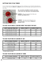
B
A
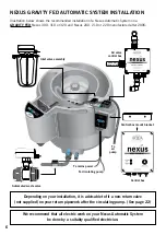
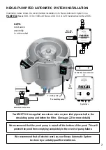
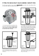
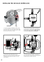
1. The Nexus Automatic Control Box should be
positioned in between the inlet and outlet of the
Nexus in either position A or B as shown. We
recommend installing it in position A.
NOTE:
Take care not to pull on any connector wires
during installation.
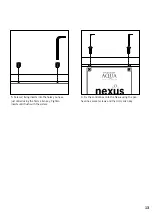
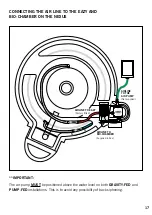
4.
Move the control box away and then drill 2 holes
into the positions you have marked using a 6mm drill.
You may need to use a knife to remove any excess
plastic or burr from around the holes you have drilled.
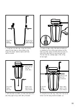
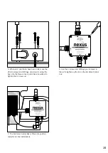
2. Use 2 x 10mm self tapping screws to fit the
stainless steel mounting bracket onto the back
of the control box to allow the control box to be
mounted to the Nexus. (These are the 2 inner
holes on the stainless steel bracket that align
with the box mounts).
B
A
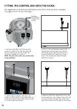
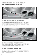
3. Hold the Nexus Automatic control box in the
position you want it located on the Nexus. Now use a
marker pen to make 2 marks where the screw holes
are on the stainless steel bracket.
FITTING THE CONTROL BOX ONTO THE NEXUS
We suggest that you familiarise yourself with the inside of the control box prior to installation.
See pages 23 to 27 for more information.
12
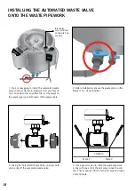
Inlet valve
only installed
on Gravity Fed
set-ups.


