background image


Contents 

Chapter 1 Product Introduction.....................................................................................1


Overview .............................................................................................................1


Main Functions....................................................................................................1


Power Feature......................................................................................................2


Main Performance ...............................................................................................2


Mounting Mode...................................................................................................3


Requirements of Transportation and Storage.......................................................3


Chapter 2 Installation....................................................................................................5


Product Outline....................................................................................................5


Product Appearance and Installation Dimensions ...............................................5


External Connectors ............................................................................................6


Overall Assembly Drawing .................................................................................7


Installing the Cover .............................................................................................8


Installing and Removing the Motherboard ..........................................................8


Installing the Drivers ...........................................................................................9


Installing the Power...........................................................................................11


Installing the Fan ...............................................................................................13


Installing the Dust-proof Net.............................................................................14


Installing the Foot Pad.......................................................................................14


Installing the Wall-mounted Bar........................................................................15


Chapter 3 Installing the Drivers..................................................................................17


Summary of Contents for IPC-6805E

Page 1: ...IPC 6805E 壁挂式兼容机箱 Compatible Wall Mount Chassis Version C01 ...

Page 2: ...不当而导致的 直接 间接 有意或无意的损坏及隐患概不负责 订购产品前 请向经销商详细了解产品性能是否符合您的需求 EVOC 是研祥智能科技股份有限公司的注册商标 本手册所涉及到的其他商 标 其所有权为相应的产品厂家所拥有 研祥智能科技股份有限公司 2011 版权所有 违者必究 未经许可 不得 以机械 电子或其它任何方式进行复制 欲获更多信息请访问研祥网站 http www evoc com或向研祥技术支持邮箱 support evoc com 国际 support evoc cn 国内 咨询 免费客服热线 4008809666 ...

Page 3: ...不必要的损伤 关机后 应至少等待 30 秒后 再开机 7 如果要进行升级或拆装等动作 须在静电放电工作台上完成所有操作 因 为有些精密器件对静电放电 ESD 很敏感 8 如果没有静电放电工作台 可通过以下方法降低 ESD 可能造成的危害 a 戴上一条防静电腕带并与相应产品的金属部分相连 b 在触摸产品部件前 先触摸相应产品机箱上的金属壳 c 当插拔部件时 身体最好与产品的金属机箱保持接触 以释放静电 d 避免不必要的走动 e 拿产品部件 尤其是板卡 时仅拿住边缘 f 将产品部件置于一个接地的无静电的操作平台上 如果可能的话 使 用一块导电泡沫垫 非部件的包装材料 g 不要让部件在操作平台上滑动 9 用十字螺丝刀进行操作 最好是强力螺丝刀 带磁性 避免螺丝遗留在机 箱内 要注意的是 一定不要将工具或零件遗漏在机箱内 10 保证系统良好的散热与通风 11 非专业维修人员不得打开机箱 ...

Page 4: ...目 录 第一章 产品介绍 1 简介 1 主要功能介绍 1 电源特性 1 主要性能指标 2 安装方式 3 运输与贮存要求 3 第二章 安装说明 4 产品外观图 4 产品外形及安装尺寸图 4 外部控制接口图 5 整体装配图 6 开盖安装 7 主板安装和拆卸 7 驱动器安装 8 电源安装 10 风扇安装 11 防尘网安装 12 脚垫安装 12 壁挂条安装 13 第三章 驱动程序安装说明 15 ...

Page 5: ... 主要功能介绍 机箱自带接口及按键 前置 2 个双 USB 2 0 接口 ATX 船型开关 复位开关 电源 硬盘指示灯 带锁安全门 扩展性能 可安装主板 PICMG 1 0 标准全长卡 PICMG 1 3 标准全长卡 EPI 2 0 标准 全长卡 EPE 标准全长卡 EC7 标准单板 可安装底板 6 槽标准 PICMG 1 0 底板 5 槽标准 PICMG 1 3 底板 4 5 槽 标准 EPI 2 0 底板 4 槽标准 EPE 底板 可安装电源标准 PS2 ATX 电源 标准 PS2 AT 电源 Mini 冗余电源 1U 电源 EC7 主板 存储扩展 1 个笔记本超薄光驱 1 个 3 5 HDD 空间 1 个笔记本超薄光驱 1 个 2 5 HDD 空间 冗余电源时 电源特性 输入电压 频率 220VAC 50Hz 整机功耗 ...

Page 6: ...R EPE 6105E2 时 26 8 W 待机状态 整机功耗 91 8 W MaxPower 100 注 搭配不同的板时功耗不一致 主要性能指标 机械尺寸 重量与环境 外形尺寸 397mm 长 174mm 宽 265mm 高 净重 1 整机搭配 PCI 6106E3 时净重 8 35Kg 2 整机搭配 EPE 6105E2 时净重 10 35kg 注 搭配不同的板净重不一致 工作环境 温度 0 50 湿度 5 0 非凝结状态 贮存环境 温度 20 60 湿度 5 90 非凝结状态 电磁兼容性 无线电骚扰限值符合 GB9254 2008 标准 A 级 抗扰度符合 GB T 17618 2008 标准的限值 ...

Page 7: ...s 周期 安装方式 19 上架式 桌面式 台面式 嵌入面板式 壁挂式 VESA 标准支撑臂 手提便携式 其他方式___________ 运输与贮存要求 运输 包装好的产品能以任何交通工具 运往任何地点 在长途运输时不得装在敞 开的船舱和车厢中 中途转运时不得存放在露天仓库中 在运输过程中不允许和 易燃 易爆 易腐蚀的物品同车 或其他运输工具 装运 并且产品不允许经受 雨 雪或液体物质的淋湿与机械损坏 贮存 产品贮存时应存放在原包装箱内 存放产品的仓库环境温度为 0 40 相对湿度为 20 85 仓库内不允许有各种有害气体 易燃 易爆炸的产品及 有腐蚀性的化学物品 并且无强烈的机械振动 冲击和强磁场作用 包装箱应垫 离地面至少 10cm 距离墙壁 热源 冷源 窗口或空气入口至少 50cm ...

Page 8: ...第二章 安装说明 4 IPC 6805E 第二章 安装说明 产品外观图 产品外形及安装尺寸图 单位 mm ...

Page 9: ...第二章 安装说明 IPC 6805E 5 外部控制接口图 前面板 后面板 A 后面板 B ...

Page 10: ...第二章 安装说明 6 IPC 6805E 整体装配图 1 箱盖 2 中压条 3 光驱硬盘支架 4 USB 5 门 6 门锁 7 铰链 8 灯板 9 电源开关 10 防尘网前盖板 11 前压条 12 箱体 13 安装条 14 后盖板 15 后压条 16 PS2 电源架 17 可调节压条 18 电源 ...

Page 11: ...第二章 安装说明 IPC 6805E 7 开盖安装 用手拧开 2 个松不脱螺丝 向后抽拉箱盖 即可将箱盖打开 主板安装和拆卸 主板安装 1 将箱盖松不脱螺丝用手拧开 打开箱盖 2 将前压条 中压条 后压条分别拆下 并安装上橡胶弹压垫 根据不 同的主板可以调整弹压垫的位置 3 将箱体自带的主板插槽的键仔取下 4 插入主板 并锁上键仔螺丝 ...

Page 12: ...第二章 安装说明 8 IPC 6805E 主板拆卸 1 将前压条 中压条 后压条分别安装在箱体上 并锁紧螺丝 并注意查看弹压垫是否卡住 PCB 2 盖上箱盖 锁紧松不脱螺丝 驱动器安装 A 硬盘安装图 ...

Page 13: ... 9 1 硬盘固定在硬盘左右支架上 并收紧螺丝 注意硬盘支架的放置方向 2 将固定好的硬盘安装在硬盘主支架的 4 个油囊减震垫上 并收紧螺丝 3 将当线板固定在主支架上 并收紧螺丝 4 将安装好的硬盘组件安装在箱体里 在侧壁固定 4 个螺丝 1 2 3 4 B 光驱安装图 1 A 将光驱孔挡板螺丝拆下 1 2 3 2 B 将光驱锁在光驱支架上 4 个 M2 螺丝 并收紧螺丝 3 C 将锁好的光驱安装在箱体里 1 2 3 4 并收紧螺丝 ...

Page 14: ...放入箱体 将电源与后挡板对应孔位放 4 个螺丝 1 2 3 4 英制 螺丝 并收紧螺丝 2 将电源支架与箱体侧壁孔位对齐 2 个螺丝 5 6 芥子头螺丝 并收紧螺丝 B 专用迷你型冗余电源 尺寸 185 150 86 1 将电源冗余电源自带的后支架和侧支架用电源自带螺丝固定在冗余电源上 并收紧螺丝 2 将冗余电源放入箱体 备注安装冗余电源时需要去掉 PS2 电源支架 3 将电源与后挡板固定 5 6 7 8 英制螺丝 4 将电源后支架与箱体侧壁的铆柱对齐并收紧螺丝 1 2 芥子头螺丝 ...

Page 15: ...第二章 安装说明 IPC 6805E 11 C 1U 电源 1 将 1U 电源放入箱体 将电源与后挡板对应孔位放 4 个螺丝 3 4 5 6 英制 螺丝 并收紧螺丝 2 将电源支架与箱体侧壁孔位对齐 2 个螺丝 1 2 芥子头螺丝 并收紧螺丝 风扇安装 拆掉过滤网盖板和过滤网支架 即可更换风扇 ...

Page 16: ...第二章 安装说明 12 IPC 6805E 防尘网安装 拆掉 1 2 3 4 沉头螺丝 即可更换海绵过滤网 脚垫安装 脚垫作为配件 可自行选用 与壁挂条共用芥子头螺丝 ...

Page 17: ...第二章 安装说明 IPC 6805E 13 壁挂条安装 壁挂条作为配件 可自行选用 与脚垫共用芥子头螺丝 壁挂安装支架整机竖放安装尺寸图 ...

Page 18: ...第二章 安装说明 14 IPC 6805E 壁挂安装支架整机横放安装尺寸图 ...

Page 19: ...第三章 驱动程序安装说明 IPC 6805E 15 第三章 驱动程序安装说明 本产品的驱动程序安装及主板详细信息请参考整机配套光盘 在此不做介 绍 ...

Page 20: ...tected by copyright No part of this manual may be reproduced stored in any retrieval system or transmitted in any form or by any means mechanical electronic photocopied recorded or otherwise without the prior written permission from the manufacturer Trademarks EVOC is a registered trademark of EVOC Intelligent Technology Co Ltd Other product names mentioned herein are used for identification purpo...

Page 21: ...atic discharge ESD 8 If there s no ESD worktable please take the following measures to prevent damage from electrostatic discharge ESD a Wear a antistatic wrist strap and connect it with the metal part of the corresponding product b Always touch the metal enclosure or frame before touching any components c Keep part of your body in contact with the metal enclosure to discharge the static while han...

Page 22: ...on 5 Product Outline 5 Product Appearance and Installation Dimensions 5 External Connectors 6 Overall Assembly Drawing 7 Installing the Cover 8 Installing and Removing the Motherboard 8 Installing the Drivers 9 Installing the Power 11 Installing the Fan 13 Installing the Dust proof Net 14 Installing the Foot Pad 14 Installing the Wall mounted Bar 15 Chapter 3 Installing the Drivers 17 ...

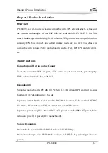
Page 23: ...ns Connectors and Buttons on the Chassis Two front accessible USB 2 0 ports ATX rocker switch reset switch power supply HDD indicator and safe door with lock Expandability Supported motherboards PICMG 1 0 PICMG 1 3 EPI 2 0 and EPE standard full size boards and EC7 standard single boards Supported carrier boards 6 slot standard PICMG 1 0 carrier 5 slot standard PICMG 1 3 carrier 4 5 slot standard E...

Page 24: ...gether with the PC Main Performance Mechanical Dimensions Weight and Environment Dimensions 397mm L x 174mm W x 265mm H Net Weight 1 Net weight when the PC is mated with PCI 6106E3 8 35Kg 2 Net weight when the PC is mated with EPE 6105E2 10 35Kg Note the net weight varies with different boards used together with the PC Operating Environment Temperature 0 C 50 C Humidity 5 90 non condensing Storage...

Page 25: ...ard Arm Portable Others___________ Requirements of Transportation and Storage Transportation Well packaged products are suited for transportation by truck ship and plane During transportation products should not be put in open cabin or carriage During transshipping products should not be stored in open air without protection from the atmospheric conditions Products should not be transported togeth...

Page 26: ... 0 C 40 C and relative humidity should be 20 85 In the warehouse there should be no harmful gas inflammable explosive products and corrosive chemical products and strong mechanical vibration shock and strong magnetic field interference The package box should be at least 10cm above ground and 50cm away from wall thermal source window and air inlet ...

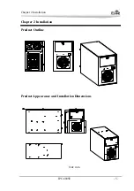
Page 27: ...Chapter 2 Installation IPC 6805E 5 Chapter 2 Installation Product Outline Product Appearance and Installation Dimensions Unit mm ...

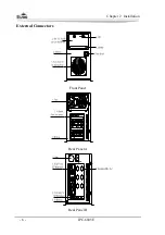
Page 28: ...Chapter 2 Installation 6 IPC 6805E External Connectors Front Panel Rear Panel A Rear Panel B ...

Page 29: ...ing 1 Cover 2 Mid Batten 3 DVD ROM Bracket 4 USB 5 Door 6 Lock 7 Hinge 8 LED Board 9 Power Switch 10 Front Cover for the Dust proof Net 11 Front Batten 12 Chassis 13 Mounting Bar 14 Rear Cover 15 Rear Batten 16 PS2 Power Bracket 17 Adjustable Batten 18 Power ...

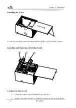
Page 30: ... two captive screws by hands and then pull the cover backward to open it Installing and Removing the Motherboard Installing the Motherboard 1 Loosen the captive screws by hands to open the cover 2 Remove the front mid and rear battens respectively and then install the ...

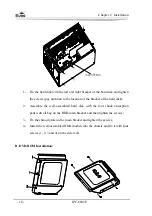
Page 31: ... slot enclosed with the chassis 4 Insert the motherboard and fasten the screws on the slot cover Removing the Motherboard 1 Install the front mid and rear battens on the chassis respectively and tighten the screws Please check whether the PCB has been buckled by the spring pad 2 Put on the cover and fasten the captive screws Installing the Drivers A Hard Disk Installation ...

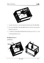
Page 32: ...racket of the hard disk 2 Assemble the well assembled hard disk with the four shock absorption pads with oil bag on the HDD main bracket and then tighten the screws 3 Fix the shroud plate on the main bracket and tighten the screws 4 Install the well assembled HDD module into the chassis and fix it with four screws 1 2 3 and 4 on the side wall B DVD ROM Installation ...

Page 33: ...ng the baffle on the slot of the DVD ROM 2 B fix the DVD ROM on the DVD ROM bracket by four M2 screws and then tighten the four screws 3 C install the well assembled DVD ROM into the chassis by screws 1 2 3 and 4 and then tighten the screws Installing the Power A PS2 Power ...

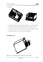
Page 34: ...6 truss head screws B Exclusive Mini type Redundant Power Size 185 150 86 1 Fix the rear bracket and the side bracket enclosed with the redundant power with the redundant power by enclosed screws and fasten them 2 Lay the redundant power into the chassis please remove the PS2 power bracket before installing the redundant power 3 Fix the power with the rear baffle 5 6 7 and 8 BS screws 4 Align the ...

Page 35: ...BS screws into the holes between the power and the rear baffle and tighten the screws 2 Align the holes on the power bracket with that on the side wall of the chassis insert and tighten the two screws 1 and 2 truss head screws Installing the Fan Remove the cover and the bracket of the filter net to replace the fan ...

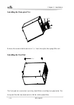
Page 36: ...oof Net Remove the counter sunk head screws 1 2 3 and 4 to replace the sponge filter net Installing the Foot Pad The foot pads are accessories users may install them according to requirements The foot pads share the truss head screws with the wall mounted bars ...

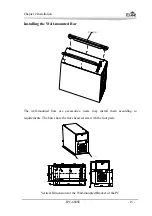
Page 37: ...15 Installing the Wall mounted Bar The wall mounted bars are accessories users may install them according to requirements The bars share the truss head screws with the foot pads Vertical Dimension for the Wall mounted Bracket of the PC ...

Page 38: ...Chapter 2 Installation Horizontal Dimension for the Wall mounted Bracket of the PC 16 IPC 6805E ...

Page 39: ...第三章 驱动程序安装说明 IPC 6805E 17 Chapter 3 Installing the Drivers Regarding the installation of the driver program and the detailed information of the motherboard please refer to the enclosed CD of the PC ...

Reviews: