Installation Instructions
EC3-1813CLD2NA(CHENGDU)
· 9 ·
4. JP4
~
JP6, JP8
~
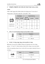
JP10: RS-232/RS-422/ RS-485 Mode Selection (Pitch:
2.0mm)
COM1, COM2 support RS-232/RS-422/RS-485 working modes. The selection of
working modes is realized by jumper JP4
~
JP6 and JP8
~
JP10.
Pin Setup
Mode Selection
COM1
COM2
RS-232
(
Default
)
RS-485
RS-422
JP4 JP8 1-2
3-4 5-6
JP5 JP9
1-3
2-4
3-5
4-6
3-5
4-6
JP4/JP5/JP6
JP8/JP9/JP10
JP6 JP10
1-3
2-4
3-5
4-6
3-5
4-6
5. JCF1: CF Card Working Voltage Selection (Pitch: 2.0mm)
Setup
Function
1-2 Short
+3.3V
JCF1
2-3 Short
+5V
(
Default
)
6. JLCD1: LCD Operating Voltage Selection (Pitch: 2.0mm)
Different LCD screens have different voltages; the board provides two voltage
options, +3.3V and +5V. Only when the selected LCD voltage is in accord with the
LCD screen operating voltage in use, can the LCD screen operate normally. Please set
as follows:
Setup
Function
1-2 Short
+3.3V(Default)
JLCD1
2-3 Short
+5V

