


Section 5
Hardee by EVH
Maintenance
LR50148 Long Reach Mower
17
CAUTION
Never vary from the 2700-psi mowerhead pressure.
Failure to comply with this specification will cause
severe hydraulic heat, loss of power and damage to
components.
DANGER
Exceeding 2700 psi will cause premature hose failure
(rupture), and possible bodily injury or property
damage.
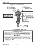
Cylinder Speeds
The LR50148 is equipped with a “Proportional
Control” feature in the main control valve that allows
the operator to control the piston speed of individual
cylinders with the amount of movement on the thumb
actuated joysticks.
Adjusting the Cylinder Control Valve
The LR50148 comes from the factory with the cylinder
control valve pre-set at the proper pressures. There is
a main relief (Item P), and seven individual cylinder
counterbalance valves (Items 5D2; 5D1; 5C2; 5C1;
5B2; 5B1; 8A2; 8A1).
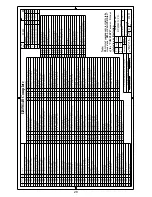
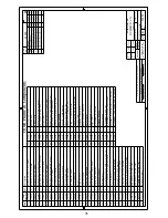
The chart on page 18 lists the
proper settings for these valves.
The procedure for checking the pressures on the
cylinder control valve is as follows:
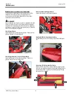
Cylinder Relief Valve (ITEM P)
Rest the deck of the LR50148 on the ground to
relieve all pressures on the hydraulic lines.
With the tractor engine off and parking brake set,
remove the hydraulic test port plug
(see page 19
for gauge port locations)
. Install a 5000 psi
pressure gauge with a SAE 4-M-ORB fitting into
the hydraulic test port and place the gauge where
you can easily see it from a safe distance.
Start the tractor and bring the engine up to
operating speed 800 (Max.1000) PTO RPM.
Activate the joystick, raise the mower deck off the
ground, and swing the boom so that it is straight
behind the tractor.
Activate the joystick in the “HEAD UP” position
until the deck cylinder fully retracts. Continue to
hold the joystick in this position for not more than
5 seconds at a time, and have someone read the
pressure on the gauge.
WARNING
While reading the gauge, be careful not to stand in an
area where inadvertent movement of the booms could
trap or crush you. If you fail to heed this warning,
SERIOUS INJURY OR DEATH COULD OCCUR
.
The correct pressure setting for the cylinder relief is
2500 psi.
To increase or decrease pressure, insert a 1/4” allen-
wrench into the adjusting stem at the top of the valve.
Loosen the 3/4” lock nut at the base of the stem
slightly, and then turn the adjusting stem to make your
pressure change. Re-tighten the stem lock nut
Note:
The allen-head adjusting stem increases
pressure when turned clockwise and decreases
pressure when turned counterclockwise. Pressure
increases or decreases rapidly with only a slight
movement. Move adjusting stem in increments of 1/4
turn or less.
CAUTION
NEVER attempt to adjust the valve when in the “on”
(loaded) position. Always make adjustments in the
“off” (neutral) position with the tractor engine turned
off.
When 2500 psi is obtained, retighten the jam nut.
Then re-test the pressure to be sure 2500 psi is
retained.
When the adjustment is complete, rest the cutter
deck back on the ground to relieve pressure in the
hydraulic lines. Remove the pressure gauge and
re-install the hydraulic test port plug.
Individual Cylinder Counterbalance Valves
(
5D2;
5D1; 5C2; 5C1; 5B2; 5B1; 8A2; 8A1;)
Each cylinder has counterbalance valves that provide
both work port relief and load control. These valves
are 100% inspected and pre-set from the factory to
ensure the proper settings. Do not alter the settings on
these valves.
If you need assistance, contact your local Hardee
dealer.
Summary of Contents for HARDEE LR50148
Page 29: ...26...
Page 30: ...Section 6 Hardee by EVH Troubleshooting LR50148 Long Reach Mower 27...
Page 43: ...40...
Page 44: ...41...
Page 45: ...42...
Page 46: ...43...
Page 47: ...44...
Page 49: ...46 Section 8 Replacement Parts...
Page 50: ...6857 6 27 18 47...
Page 55: ...NOTES...


