EVH MFG HARDEE LR50148 Operator And  Maintenance Manual Download Page 16

Section 4 

Hardee by EVH 

Operation Instruction 


LR50148 Long Reach Mower 

13 


The terrain and the kind of material being cut will 
determine your ground speed. Remember that you will 
need to raise and lower the mowerhead to follow the 
ground contour you are cutting. 


Boom Breakaway 

The LR50148 is designed with an automatic 
breakaway system to protect the mower booms. This 
works when the mowerhead contacts a solid 
obstruction or the mowerhead is “grounded” while the 
tractor is in motion. The breakaway is activated 
through the hydraulic valve and will function mowing 
both forward and backward. 
 
When the mowerhead strikes a solid object the booms 
will begin to break back, IMMEDIATELY stop your 
tractor and adjust the position of the booms to clear 
the object. 
 
If you “ground” the mowerhead and the booms begin 
to break back, simply lift the boom slightly to free the 
mowerhead, then swing the boom back into normal 
mowing position. 

See figure 2 


Figure 2 


Mowing in Reverse 

Your Hardee unit can cut as easily when the tractor is 
moving in reverse as forward. The breakaway 
protection works in the same way. The only difference 
being you must swing the booms to the rear 10 – 15 
degrees. This will allow for more boom breakaway 
travel. This space is critical so as not to bottom-out the 
boom arm. 

See figure 3 


Caution 

You will do severe damage to your mower if you allow 
the boom arm to reach the bottoming-out point! 


Figure 3


Caution 

You must allow for the extra boom travel when 
mowing in reverse. See figure 3. If you have any 
questions about these instructions, please ask your 
local Hardee dealer immediately! Warranty claims for 
equipment used improperly will not be accepted.
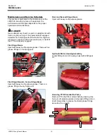


Side Dressing Trees 

The design of your heavy-duty brush mower will allow 
you to “side dress” trees if needed. To do this, raise 
the booms to the desired height and tilt the 
mowerhead to the vertical position. With the blades 
“on” move forward slowly, removing only 
approximately 12 inches of material per pass. 


DANGER


Never operate the mower within 10 feet of overhead 
power lines or utility lines. Do not trim trees with power 
lines running through them. Serious injury or death by 
electrocution may occur.


Cutting Larger Brush and Trees 

A  unique  feature  on  the  LR50148  is  the  mowerhead 
“HINGED GATE”. The “HINGED GATE” is used when 
you  need  to  remove  trees  as  large  as  4  inches  in 
diameter.  This  is  accomplished  in  the  following 
manner: 

  Be  sure  that  the  mower  blades  and  tractor  are 

turned “OFF”. 

  Unlock the “HINGED GATE” by removing the two 

bolts. 

Refer to Figure 5 & 6 on Page 14.


  Replace  one  bolt  on  the  main  deck  for  storage 

and  use  the  second  bolt  to  lock  the  gate  in  its 
raised up position.  

Maximum Travel 

Normal Mowing 

Position 

Available 

Breakaway 

Breakaway 

Normal Mowing 

Position 

Direction of 

Travel 

Direction of 

Travel 

Summary of Contents for HARDEE LR50148

Page 1: ...ower Model LR50148 DANGER Read this manual and the manual for your tractor carefully to acquaint yourself with both machines before operating 4895 RED BLUFF RD LORIS SC 29569 843 756 2555 www hardeeby...

Page 2: ...ailure of components in the hydraulic control valve pump and motor Disclaimer THIS MOWER IS NOT DESIGNED TO CUT TREES FROM TOP TO BOTTOM VERTICALLY WITH THE MOWER DECK IN THE HORIZONTAL POSITION See F...

Page 3: ...Do s And Don ts 11 Using Your Mower 12 Getting Started 12 Joystick Control 12 Boom Breakaway 13 Mowing In Reverse 13 Side Dressing Trees 13 Cutting Larger Brush And Trees 13 Unhook And Post Use Care...

Page 4: ...cessary Cleaning after each use and storage under a shelter will extend the life of the mower Purpose of This Manual This manual provides information on safety operation adjustments troubleshooting an...

Page 5: ...ion tipping rollover property damage personal injury or death WARNING Never stand or allow others to stand under the boom or mowerhead at any time Never park the unit without placing the mowerhead squ...

Page 6: ...u must replace any safety decals that are damaged or missing You can order replacement decals from any local Hardee dealer Just ask for part number 15845 To apply the replacement decals Clean the surf...

Page 7: ...dee by EVH Safety Information LR50148 Long Reach Mower 4 Safety Decals continued Deck Warning Rotating Components Hitch Frame Danger Crushing Hazard Hitch Frame Warning High Pressure Fluid Hazard Hitc...

Page 8: ...dee by EVH Safety Information LR50148 Long Reach Mower 5 Deck Linkage Deck Linkage 1 st Stage Boom 1 st Stage Boom Warning Pinch Point Deck Blade Rotation Hitch Frame Danger Crushing Hazard Safety Dec...

Page 9: ...ng Reach Mower 6 Safety Decals continued Deck Danger Keep Clear Danger Electrocution Falling and Crushing Hazard Hitch Frame Deck Danger Exposed Blades 15852 Red Reflector Rear Not Shown Deck Front Re...

Page 10: ...Breather N Motor Drive Housing C Oil Tank O Rubber Shielding D Return Filter P 2 nd Stage Reach Boom E Swing Cylinder Q 2 nd Stage Cylinder F Hitch Frame R Lift Break Away G Swing Post S 1 st Stage Cy...

Page 11: ...mp shaft to the PTO connection of your tractor This step may require cutting the standard driveshaft included with the Hardee mower We recommend contacting your local Hardee dealer for assistance Driv...

Page 12: ...the mower pump powers ALL hydraulic functions A Programmable Processor Refer to Page 25 controls four cylinder functions swing first stage boom lift second stage boom lift and mower deck tilt and one...

Page 13: ...GREEN LED COMES ON THEN RELEASE DEAD MAN BAR 3 0 HOLD DOWN THE CUTTER HEAD SWITCH ENGINE SHOULD BE SHUT OFF WHILE PUSHING THE LEFT JOYSTICK 1 UP AND THE RIGHT JOYSTICK 2 DOWN FOR 5 SECONDS THE GREEN L...

Page 14: ...All Fluid Levels Tractor Mower For best results use Hardee hydraulic oil part number 23333 Grease Points Page 15 PTO Shaft Check Grease Page 15 Blade Tightness Page 16 Operating Environment Applicatio...

Page 15: ...carrier castle nut and both blade bolts for tightness Verify that the gate valve under the oil tank is on The mower is shipped with the gate valve in the off position Danger Before proceeding make sur...

Page 16: ...figure 3 Caution You will do severe damage to your mower if you allow the boom arm to reach the bottoming out point Figure 3 Caution You must allow for the extra boom travel when mowing in reverse See...

Page 17: ...me no more than two or three feet in length per pass See fig 5 Unhook and Post Use Care Before unhooking the tractor from your mower always clean the unit thoroughly to remove any grass mud or debris...

Page 18: ...rious personal injury or death if the PTO accidentally engages First Stage Boom Inject with heavy multi purpose grease There are five grease fittings on the swing post First Stage Boom to Second Stage...

Page 19: ...reakdown drawing on page 37 for reference Checking the Mower Head Relief Valve The LR50148 is equipped with a mowerhead relief valve that comes pre set from the factory This valve is installed in the...

Page 20: ...Activate the joystick in the HEAD UP position until the deck cylinder fully retracts Continue to hold the joystick in this position for not more than 5 seconds at a time and have someone read the pre...

Page 21: ...ft lbs Q Pilot Opp Dir Valve 6 80 ft lbs 2 5 ft lbs R Return Port T S Pump Port P T Deck Motor Pressure Port MP U Deck Motor Return Port MPR NOT SHOWN NOT SHOWN NOT SHOWN NOT HITCH FRAME WIRING HARNE...

Page 22: ...A B C D K J I H G F E O P Q 19 8A1 8A2 5B1 5B2 5C1 5C2 5D1 5D2 FV 8099 4A 4B 4C 4D M U R S L T N CONTROL VALVE PORT SCHEMATIC LR50148 Long Reach Cutter Section 5 Maintenance Hardee by EVH Guage Port...

Page 23: ...1st Stage Up 5B1 B Top White C17 Up N 1st Stage Down 5B2 B Bottom White C16 Down S 2nd Stage Down 5C1 C Top White C12 Down S 2nd Stage Up 5C2 C Bottom White C11 Up N Deck Down 5D1 D Top White C15 Left...

Page 24: ...Blade Holder Torque to Spec on Blade Holder Breakdown Blade Holder Nut Torque to Spec on LR50148 Parts Breakdown Spindle Bolts Spindle To Deck Main Frame And Deck Bolts Daily Or 10 Hours Rubber Shiel...

Page 25: ...etting Check Relief Valve Setting Refer To Pages 18 19 Proportional Valve Repair Replace Relief Valve Check for trash or Replace Poppet Valve in Motor Check Replace Poppet valves in motor Pump Whines...

Page 26: ...nside Cigarette Lighter Plug Replace Fuse Filter Gauge Is In The Red At All Times Filter Restricted Repair Replace Filter Bad Gauge Repair Replace Gauge Hydraulic Oil Too Heavy For Region Or Climate R...

Page 27: ...wires 32 Proportional Unloader Output Open or Short Circuit Check valve coil and wires 33 Head Down Swing Right Output Open or Short Circuit Check valve coil and wires 34 Head Up Swing Left Valve Outp...

Page 28: ..._________________________________________________________________ ___________________________________________________________________________________ Section 6 Troubleshooting Hardee by EVH LR50148 Lo...

Page 29: ...26...

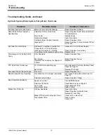
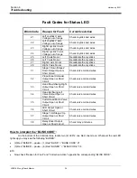
Page 30: ...Section 6 Hardee by EVH Troubleshooting LR50148 Long Reach Mower 27...

Page 31: ...In Diameter Mowing Width 48 Deck Height 8 1 8 Deck Thickness 10 Gauge Driveline Category 3 Driveline Protection Hydraulic Relief Valve Hitch Standard Hitch Category 2 Or 3 Quick Hitch Motor Hydraulic...

Page 32: ...845 79 15845 11 1 WARNING DECAL KIT 15845 80 15845 15 1 DANGER DECAL KIT 15845 81 15845 16 2 DANGER DECAL KIT 15845 82 15845 9 1 WARNING DECAL KIT 15845 83 15852 2 Red Reflector Decal 84 15853 2 Yello...

Page 33: ...ess Otherwise Specified Dimensions in are in Millimeters REV CHANGE BY DATE ECN IR INITIAL RELEASE T B B 10 23 15 1635 A Stand Weldment Replaced 23160 was 23038 T B B 1 19 16 1620 B Pump 15240 Has Cha...

Page 34: ...pple 32 13902 8 STRAIGHT 6 M JIC X 8 M ORB 33 13974 1 16 M JIC X 16 M NPT 90 Deg Elbow 34 15466 2 Tubing Insert 3 1 2 Sqr X 11 35 15845 15 1 DANGER DECAL KIT 15845 36 15845 16 1 DANGER DECAL KIT 15845...

Page 35: ...16 1620 B Pump 15240 Has Changed To Pump 16705 T B B 12 14 16 1672 Cylinder 10448 Has Changed To Cylinder 16747 T B B 1 16 17 1655 C Cylinder 15928 Has Changed To Cylinder 16750 Cylinder 10454 Has Cha...

Page 36: ...nd Weldment 18 25724 2 WELDMENT Cylinder Pin 19 25930 1 ASSEMBLY Hitch Frame LR50160 LR50148 Item Part Number Qty Description A 10092 1 HEX BOLT 5 8 X 2 GR 5 PLATED B 10204 4 FLAT WASHER 1 2 Plated US...

Page 37: ...16751 1 CYLINDER 4 X 24 TIE ROD Long Rod LR 10 16845 1 Cylinder 4 X 24 With 2 0 Rod 11 23280 1 WELDMENT Cylinder Breakaway 12 23294 1 1st Stage Boom 13 23349 1 Outer Hose Guard Weldment 14 23352 1 Inn...

Page 38: ...ivot Sleeve 10 23131 1 End Cap Weldment 11 23287 2 Boom To Deck Bracket Weldment 12 23290 2 WELDMENT Boom to Deck Bracket 21 13 23292 1 PIN WELDMENT 1 x 5 LG 14 23310 1 2nd Stage Boom 15 23345 1 Head...

Page 39: ...Body SET OF 2 23 15255 2 Hose Clamp Cover Plate 24 15338 1 Danger Decal Exposed Blades 25 15481 1 Slotted Hex Nut 1 1 4 18UNEF 26 15845 1 1 DANGER DECAL KIT 15845 27 15845 10 1 WARNING DECAL KIT 15845...

Page 40: ...NING DECAL KIT 15845 37 15845 11 1 WARNING DECAL KIT 15845 38 15845 15 1 DANGER DECAL KIT 15845 39 15845 16 1 DANGER DECAL KIT 15845 40 15845 9 1 WARNING DECAL KIT 15845 41 15910 46 HOSE SLEEVE 42 160...

Page 41: ...C Cylinder 15928 Has Changed To Cylinder 16750 Cylinder 10454 Has Changed To Cylinder 16751 T B B 2 3 17 1675 D 16845 REPLACED 16750 Hyd Cylinder V A M 8 11 17 1686 D 25925 DWG NO Blade Hydraulics Oi...

Page 42: ...tion Key Part No Description 1 N A Housing 8 16480 Set Screw 2 N A Shaft 9 16491 Lip Seal Output 3 15952 Cup 10 16488 Seal Protector 4 15953 Bearing 11 16580 Blade Hub 5 16492 Washer w tang 12 15481 N...

Page 43: ...40...

Page 44: ...41...

Page 45: ...42...

Page 46: ...43...

Page 47: ...44...

Page 48: ...al away from the paper backing Press firmly onto the clean surface Squeeze out any air pockets using a straight edge Logo Decals If the original decals applied to your mower at the factory become worn...

Page 49: ...46 Section 8 Replacement Parts...

Page 50: ...6857 6 27 18 47...

Page 51: ...Description 301 15579 Push Pin complete 305 16708 1 3 8 21 yoke w swell pin cat 4 302 15900 1 3 8 21 spline yoke tractor end 16765 Swell Pin Kit For 16708 303 11437 Cross Kit 306 15804 Shield bearing...

Page 52: ...bolt torque are not applicable in cases where bolts are used as a pin like device holding together two or more movable objects and keeping them from spreading apart Clamping Torque Being dependent upo...

Page 53: ...70 297 420 567 243 474 668 402 370 705 995 1343 378 721 1019 1376 536 890 1444 1950 747 1241 2012 2716 1007 1672 2712 3661 1322 2194 3557 4802 1 14 280 973 1 3 8 12 746 2257 1 1 2 12 979 2962 1 1 8 12...

Page 54: ...e implement made without the written authorization of the manufacturer will render this warranty void Tampering with or removing the factory installed hour meter will void this warranty This warranty...

Page 55: ...NOTES...

Page 56: ...EVH MANUFACTURING COMPANY LLC 4895 RED BLUFF ROAD LORIS SC 29569 PHONE 843 756 2555 OR 1 888 990 2555 WWW HARDEEBYEVH COM INFO HARDEEBYEVH COM...

Reviews: