evertz EQX-IP18-IPG User Manual Download Page 41

EQX–IP18-IPG 

EQX Input and IP Gateway Module 


Revision 1.0


Page - 31 

7.8. 

IP INPUT CONTROL 

This section will allow the user to monitor or configure the IP input parameters. 


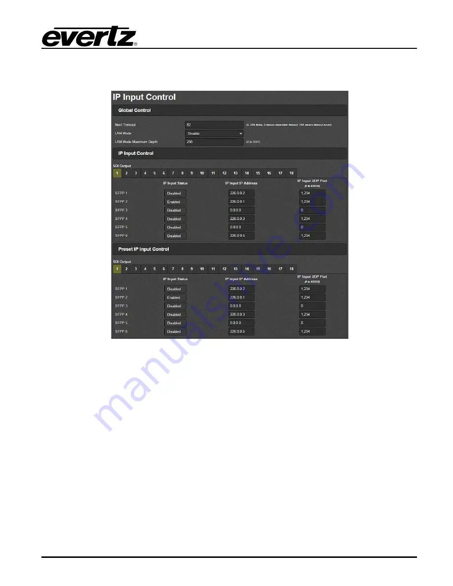
Figure 7-20: IP Input Control Tab 


7.8.1.  Global Control 

Next Timeout 

  This control is used to set the 

Next Timeout

.  A value of 0 means immediate timeout while a 

value of 255 means timeout never. 


LAN Mode 

  This control is used to 

Enable

 or 

Disable 

the LAN Mode Maximum Depth. Refer to  glossary 

in section 7 for an explanation.


LAN Mode Maximum Depth 

  This control is used to set the value for the LAN Mode Maximum Depth.  Refer to Glossary in 

section 7 for an explanation. 


Summary of Contents for EQX-IP18-IPG

Page 1: ... purchasers of the EQX IP18 IPG product Evertz Microsystems expressly prohibits the use of this guide for any purpose other than the operation of the contained in this reference guide consists of information that is the property of Evertz Microsystems and is intended solely for the use of purchasers of the EQX IP18 IPG product Due to on going research and development features and specifications in...

Page 2: ...This page left intentionally blank ...

Page 3: ...ird grounding prong The wide blade or the third prong is provided for your safety If the provided plug does not fit into your outlet consult an electrician for replacement of the obsolete outlet Protect the power cord from being walked on or pinched particularly at plugs convenience receptacles and the point where they exit from the apparatus Only use attachments accessories specified by the manuf...

Page 4: ... Class A digital device pursuant to Part 15 of the FCC Rules These limits are designed to provide reasonable protection against harmful interference when the equipment is operated in a commercial environment This equipment generates uses and can radiate radio frequency energy and if not installed and used in accordance with the instruction manual may cause harmful interference to radio communicati...

Page 5: ...TOM HALF OF AN EQX26 FRAME 9 5 SETTING GENLOCK REFERENCE 11 5 1 NTSC REFERENCE 11 5 2 PAL REFERENCE 12 6 CHECKING INPUT STATUS WITH LEDS ON THE MODULE 13 7 WEB INTERFACE CONFIGURATION 15 7 1 LOGIN 15 7 2 SYSTEM TAB 16 7 2 1 Data Port Configuration 16 7 2 2 Data Port Monitor 16 7 2 3 Rear Panel 17 7 2 4 SFP Monitor 18 7 2 5 Genlock Configuration 19 7 2 6 Genlock Monitoring 19 7 2 7 Temperature 19 7...

Page 6: ...ntrol 32 7 9 IP INPUT MONITORING 33 7 9 1 IP Input Monitoring 33 7 9 2 IP Input Monitoring 33 7 10 SDI OUTPUT 34 7 11 1 Router Source 34 7 11 2 Router Source 35 7 11 3 SDI Output Global 35 7 11 4 SDI Output Control 35 7 11 5 SDI Output Monitoring 36 7 11 6 SDI Port Control 36 7 12 VIDEO NOTIFY 37 7 12 1 Video Monitoring Control 37 7 12 2 Video Input Notify 37 7 12 3 Video Output Notify 37 7 13 AUD...

Page 7: ...el 18 Figure 7 5 SFP Monitor 18 Figure 7 6 Genlock Configuration 19 Figure 7 7 Genlock Monitoring 19 Figure 7 8 Temperature 19 Figure 7 9 Trap Destination 20 Figure 7 10 Standard Control 20 Figure 7 11 Configuration Management 22 Figure 7 12 License Tab 23 Figure 7 13 Web Interface Input Route Control Tab 1 24 Figure 7 14 Web Interface Input Route Control Tab 2 25 Figure 7 15 Web Interface Output ...

Page 8: ...EQX IP18 IPG EQX Input and IP Gateway Module Page iv Revision 1 0 TABLE OF CONTENTS This page left intentionally blank ...

Page 9: ...rranty offered by Evertz in relation to this product is the Evertz standard limited warranty stated in the sales contract or order confirmation form Although every attempt has been made to accurately describe the features installation and operation of this product in this reference guide no warranty is granted nor liability assumed in relation to any errors or omissions unless specifically underta...

Page 10: ...EQX IP18 IPG EQX Input and IP Gateway Module Page vi Revision 1 0 This page left intentionally blank ...

Page 11: ...ully hotswappable and accessed from the front of the EQX frame The EQX router can be loaded with a maximum of 32 EQX IP18 IPG modules providing square and non square matrix configurations from as small as 18 inputs through to 576 inputs The EQX IP18 IPG hybrid input card provides a gateway to link into IP infrastructures as well as allow a more efficient way to tieline routers together IP based vi...

Page 12: ...6 SFP Connectors The six SFP data ports are bi directional and can be used for both encapsulation and de encapsulation for the SDI streams Supports SMPTE ST 259 SMPTE ST 292 1 and SMPTE ST 425 1 Level A input and output signals AUDIO CONNECTIONS 2 TDM Outputs Two Mini DIN connectors for TDM audio compatible with Evertz TDM v2 only Note EQX IP18 IPG only supports the RPC based system All input and ...

Page 13: ...orts 6 x SFP Impedance 75 Ω terminating Input Equalization SD Standards Automatic to 190m 270Mb s with Belden 1694 or equivalent cable HD Standards Automatic to 135m 1 5Gb s with Belden 1694 or equivalent cable 3G Standards Automatic to 90m 3Gb s with Belden 1694 or equivalent cable DC Offset 0 0 5 V Output Jitter SD Standards 0 2 UI HD Standards 0 2 UI 3G Standards 0 3 UI 2 2 ELECTRICAL Voltage 4...

Page 14: ...EQX IP18 IPG EQX Input and IP Gateway Module Page 4 Revision 1 0 This page left intentionally blank ...

Page 15: ... 10 RU frame EQX platform can be expanded beyond its standard routing capability by adding X Link expansions to the frame The most common frame types are as follow 1 Standard 26RU 16RU and 10RU frames 2 26RU frames with Xlink expansion outputs 3 16RU frames with Xlink expansion outputs 4 10RU frames with Xlink expansion outputs For more information on EQX frames see the EQX Series manual Figure 3 ...

Page 16: ...EQX IP18 IPG EQX Input and IP Gateway Module Page 6 Revision 1 0 This page left intentionally blank ...

Page 17: ...ng on the top verses the bottom of the EQX26 frame 4 1 INSTALLATION OF REAR PLATE OR MODULE INTO TOP HALF OF A EQX26 FRAME Most of the time cards come preinstalled in the frame if both frame and the cards are ordered together In the case of installing spare cards and rear plates into the frame the following steps need to be taken into consideration Step 1 Install the EQX IP18 IPG rear plate to the...

Page 18: ...n to the top half of the EQX frame and make sure the orientation of the card is the same as shown in Figure 3 2 Figure 4 2 Illustration EQX IP18 IPG Installed in the Top Slot Note Orientation of the rear plate and EQX IP18 IPG module are the same in EQX16 and EQX10 frame as in the top half of EQX26 frame ...

Page 19: ...LATE OR MODULE INTO BOTTOM HALF OF AN EQX26 FRAME Step 1 Install the EQX IP18 IPG rear plate to the EQX frame with screws provided and make sure the orientation of the rear plate is the same as shown in Figure 4 4 3 Figure 4 3 Rear Plate Orientation When installing to the Bottom of the Frame ...

Page 20: ...ule Page 10 Revision 1 0 Step 2 Insert the EQX IP18 IPG module in to the bottom of the EQX26 frame and make sure the orientation of the card is the same as shown in Figure 4 4 4 Figure 4 4 Illustration EQX IP18 IPG Installed in the Bottom Slot ...

Page 21: ...to open or closed When a dip switch is up means the open position is selected When a dip switch is down means the closed position is selected Figure 5 5 2 illustrates the open position Figure 5 2 Illustration of Dip Switch 5 1 NTSC REFERENCE Step 1 Make sure the NTSC reference signal is provided to the EQX frame Step 2 Set the dip switch at the EQX IP18 IPG card edge position to the following Swit...

Page 22: ...8 IPG card edge position to the following Switch State 1 Open 2 Open 3 Open 4 Open Table 5 2 Card Edge Dip Switch Settings for PAL Reference Note It is a recommended practice to provice both NTSC and PAL reference to the frame at the same time Note The reference dip switch has to be set correctly based on the incoming video misconfiguration of the dip switch will result in malfunctioning of IPG ...

Page 23: ... are split up into two columns to indicate valid input detections Whether the module is inserted in the top or bottom of the frame the left side indicates SDI detection from the DIN inputs while the right side indicates SDI detection from the Data Port inputs Figure 6 1 LED Indicators when installed in the Top half of the Frame DIN Inputs Data Port Inputs ...

Page 24: ...EQX IP18 IPG EQX Input and IP Gateway Module Page 14 Revision 1 0 Figure 6 2 LED Indicators when Installed in the Bottom half of the Frame DIN Inputs Data Port Inputs ...

Page 25: ...b interface is explained in the following sections 7 1 LOGIN Make sure IPG is pingable from PC and type the IP address of the card in the address bar of the browser Error Reference source not found shows the login window for EQX IP18 IPG Use customer for both the Login and Password credentials or root for login and evertz for password Figure 7 1 Web Interface Login Screen ...

Page 26: ... to set the IP Address for the specified data port NetMask This parameter allows the user to define the subnet mask for the IP address Gateway This parameter allows the user to define the gateway address for the specified data port Figure 7 2 Web Interface System Tab Data Port Configuration 7 2 2 Data Port Monitor The following fields display the current statistics on the specified data port Ether...

Page 27: ...lticast frames transmitted Video Rx Bandwidth This field displays the received Ethernet bandwidth This value is displayed in Mbps Video Tx Bandwidth This field displays the transmitted Ethernet bandwidth This value is displayed in Mbps Ethernet Link Status dB This field displays the current link status on the specified data port as either Up or Down The user can also reset the current statistics w...

Page 28: ...cal Copper 3m and Copper 5m Figure 7 4 Rear Panel 7 2 4 SFP Monitor The following fields display the status of SFP on the specified data port SFP Part Number This field displays the SFP part number detected SFP Type This field displays the type of SFP SFP Rx Power Level This field displays the receiving power level SFP Tx Power Level This field displays the transmitting power level SFP Temperature...

Page 29: ... Genlock as Locked or Unlocked Genlock Present This field will display the presence of Genlock of the specified reference Genlock Standard This field will display the Genlock standard detected If the standard is neither PAL nor NTSC the value displayed will be Unknown Figure 7 7 Genlock Monitoring 7 2 7 Temperature Board Temperature This field displays the board temperature CPU Temperature This fi...

Page 30: ... used to set the number of transmission packets per frame This options only applies to the non SMPTE 2022 standards Evertz TS and ASPEN Range is 1 7 Must apply and reboot module in order for the change to take effect Note Any changes in the Standard Control section require the module to be rebooted Figure 7 10 Standard Control 7 2 10 Configuration Management Export Configuration File This option a...

Page 31: ...ress This address can be set manually or received from magnum either way it has to match the multicat address that is defined in magnum Commands are received from magnum via this multicast address Tally IP Address This address can be set manually or received from magnum either way it has to match the multicat address that is defined in magnum Responses are sent to magnum via this multicast address...

Page 32: ...tings Purge Status This field displays whether the is ready to be purg or the purg is in progress Load Factory config This control will allow the user to reload the factory settings and will wipe out all the previous settings Reboot Card This control allow the user to reboot the card remotely Figure 7 11 Configuration Management ...

Page 33: ... used to download the product license file To download the license Choose File and click Upload Product Serial Number This field displays the product serial number Product MAC Address This field displays the product MAC address 7 3 2 Product Feature Feature 1 and 2 This field displays the product features enabled Figure 7 12 License Tab ...

Page 34: ...Input Route Control is managed by Magnum Note Each SFP is 10G and it can carry up to 3 x 3G or 6 x HD signal To Perform Take Most of the time the routes are managed by Magnum in some exceptional cases manual route can be done on the IPG as well Once the manual route is done on the Grid the Take button has to be pressed for the change to be applied Route and State Type Both Route and State Type are...

Page 35: ... Management displays the current routes configured on the module It shows which DIN SDI input is routed to which SFP output These configurations are managed by MAGNUM Note Any SDI input can be routed to any SFP out within the same module However SDI to SFP can not be routed across two different modules Figure 7 15 Web Interface Output Route Control Tab Note Output Route Control is managed by Magnu...

Page 36: ...tton to be pressed Once the take button is pressed the table under the Rotue and State Type will be cleared Un Route Future use 7 6 DIN SDI INPUTS This section is to configure and monitor the DIN SDI inputs Figure 7 16 SDI Input Tab 7 6 1 SDI Input Control SDI Input Status This field displays whether the card has the SDI Input option enabled or disabled SDI Input Bandwidth Limit This control is us...

Page 37: ...isplays the type of input signal detected Note All the above information is available for each input by selecting tabs 1 18 7 6 3 SDI Port Control SDI Alias This control allows the user to provide an Alias for each SDI Input so when there is fault in one of the inputs that particular alias will be displayed in VLPRO SDI Video Error This field displays the number of errors detected on the SDI signa...

Page 38: ...and so on IP Output Source IP Address This section displays the IP addresses of the Data Ports SFPs These IP addresses are unique for each SFP and are the same for each SDI input 1 18 IP Output Source UDP Port This control displays the source UDP port number These port could be the same IP Output Destination IP Address This control is used to configure the output destination multicast IP address T...

Page 39: ...e Type of Service number on the IP output from 0 255 IP Output Time To Live This control is used to set the Time to Live number on the IP output IP Output RTP Mode This control is used to Enable or Disable RTP Real time Transport Protocol on the IP output Figure 7 18 IP Output Advanced Control Note Magnum will set these values in the Multicast tab in SDVN ...

Page 40: ...is field displays whether there is valid data on the port by showing Active or Inactive IP Output Bits Rate Mbps This field displays bits rate on the port from the DIN SDI input selected Clear Stats The Clear Stats button is used to clear the stats recorded for IP Output bits rate Figure 7 19 IP Output Monitoring ...

Page 41: ... Control Next Timeout This control is used to set the Next Timeout A value of 0 means immediate timeout while a value of 255 means timeout never LAN Mode This control is used to Enable or Disable the LAN Mode Maximum Depth Refer to glossary in section 7 for an explanation LAN Mode Maximum Depth This control is used to set the value for the LAN Mode Maximum Depth Refer to Glossary in section 7 for ...

Page 42: ...ming stream IP Input UDP Port This control is used to specify the UDP port number associated with the incoming IP address 7 8 3 Preset IP Input Control IP Input Status This field displays the status of the SFP port as either Enabled or Disabled IP Input IP Address This control is used to specify the input IP address of the next incoming stream IP Input UDP Port This control is used to specify the ...

Page 43: ...ctive or Inactive IP Input Bits Rate Mbps This field displays the rate of incoming signal IP Input Video Standard This field displays the standard of video detected on the input IP Input RTP Present This field displays whether the input protocol is using RTP or not IP Input Signal Type This field displays the type of input signal IP Input RTP Sequence Error Count This field displays the number of ...

Page 44: ...e Core Router Source Selection This control is used to select what type of input will be used for routing The options are IP Decap Baseband Direct and Baseband Synchronized IP Decap De encapsulated signal is sourced to the EQX XPT from the Data Ports Baseband Direct Signal source to EQX XPT is directly from baseband DIN Inputs Baseband Synchronized Signal source to EQX XPT is directly from frame s...

Page 45: ... This field displays the SDI output status as either Enabled or Disabled SDI Output H Offset This control is used to adjust the horizontal offset on the SDI video output SDI Output V Offset This control is used to adjust the vertical offset on the SDI video output SDI Output Alias This control is used to give an alias name on the SDI output SDI Output Mode This control is used set the delay on the...

Page 46: ...l present and locked SDI Output Active Ethernet Port This field is used to display whether the SDI output is coming from DIN input or an SFP input 7 11 6 SDI Port Control SDI output Alias In this field user can assign an alias for each output SDI Output Video Error This field will display the number of video error on the output Reset SDI Output Video Error This button will reset the video error co...

Page 47: ... frames for freeze video before it is considered a fault 7 12 2 Video Input Notify Video Present When set True in case of signal loss a trap message will be sent to the trap addresses configured in the Trap Control section of the System tab Picture Black When set True in case of Black video a trap message will be sent to the trap addresses configured in the Trap Control section of the System tab P...

Page 48: ... is black a trap message will be sent to the trap addresses configured in the Trap Control section of the System tab OutputPicture Freeze When set True if the output video is frozena a trap message will be sent to the trap addresses configured in the Trap Control section of the System tab Figure 7 25 Video Output Notify ...

Page 49: ...lt condition is triggered Audio Silence Level 80 to 40 dBFS This control sets the threshold limit for the audio silence level before a fault condition is triggered Audio Silence Duration 1 to 128 seconds This control sets the duration for the audio silence level before a fault condition is triggered 7 13 2 Audio Input Notify Input Audio Traps Audio Pair When set True a fault condition on a Audio P...

Page 50: ...een when there is no fault on the audio and red for a fault indication 7 14 IP NOTIFY IP notify will show the current status of Ethernet port Encapsulator and Decapsulator and allow the user to enable disable SNMP trap settings Figure 7 27 IP Notify Tab 7 14 1 Ethernet Fault Enet Presence When set True if the Ethernet is missing a trap message will be sent to the trap addresses configured in the T...

Page 51: ... Output When set True an error on the Encapsulator will send a trap message to the trap addresses configured in the Trap Control section of the System tab Encapsulator Fault Present This field will display green when there is no fault and red for a fault indication 7 14 3 Decapsulator Fault SFPP 1 to 6 IP Input When set True an error on the Decapsulator will send a trap message to the trap address...

Page 52: ...gered by a missing DIN SDI Input will send a trap message to the trap addresses configured in the Trap Control section of the System tab SDI Input Faults This field will display green when there is no fault and red for a fault indication 7 15 2 Fan Notify Board Over Heat Present When set True if the board temperature exceeds the threshold limit that is set in the System tab a trap message will be ...

Page 53: ...if the CPU temperature exceeds the threshold limit that is set in the System tab a trap message will be sent to the trap addresses configured in the Trap Control section of the System tab Fan Faults This field will display green when there is no fault and red for a fault indication ...

Page 54: ... Apply This function is only available if logged as root evertz When this option is enabled any manual change will be automatically applied 7 16 1 Firmware Upgrade This section will allow the user to upgrade the module remotely Figure 7 30 Firmware Upgrade Name Displays the nam of the card Current Version Displays the current firmware loaded Choose File This button allows the user to locate the ne...

Reviews: