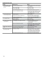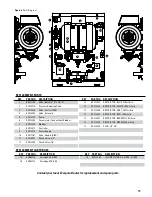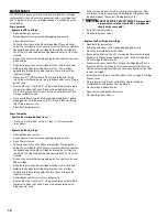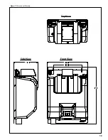
5
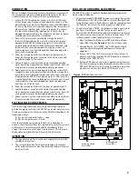
cartrIdge InStallatIon and actIVatIon
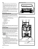
Remove the outer shrink-wrap and protective cap from the
1.
2SR-BW & MR-600 RO cartridges. Position a bucket under the
2SR -BW cartridge head. Slowly open the Inlet shut-off valve.
Apply power to the system by plugging the power cord into the
receptacle. Within moments, the display water should illuminate
and the system will go into PRESSURIZE mode. Once a solid flow
of water has been established, flush 1 gallon. Unplug power cord.
Empty bucket.
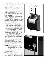
Install 2SR-BW cartridge. Align the lugs on the new cartridge
2.
with the slots in the head. Holding the head and cartridge firmly,
press the cartridge upward into the head fully, and then turn the
cartridge to the right until it stops.
Disconnect 3/8" OD line from 2SR-BW to Booster Pump inlet at
3.
Booster Pump. Route line into bucket and secure. Plug-in power
cord. Once a solid flow of water has been established, flush 1
gallon. Unplug power cord. Re-connect 3/8" OD line to Booster
Pump inlet. Empty bucket.
Route a blue line from the 3/8" storage tank drain valve to drain
4.
temporarily. Open storage tank drain valve.
Install MR-600 cartridge. Align the lugs on the new cartridge
5.
with the slots in the head. Holding the head and cartridge firmly,
press the cartridge upward into the head fully, and then turn the
cartridge to the right until it stops.
Plug-in power cord. Once a solid flow of water has been
6.
established, flush 5 gallons from storage tank drain (about 10
minutes). Unplug power cord.
WARNING
do not uSe tHIS Product Water! It may contain
a preservative solution from the ro cartridge and
should not be consumed!
recoVery adjuStment
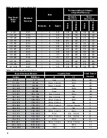
Measure the raw water TDS. Refer to Table 1 on page 6. Find
1.
the TDS range in the column labeled “Raw Water TDS” that
corresponds to your TDS measurement. Read across that row
to determine maximum recovery, permeate to reject ratio and
permeate/reject volumes.
Using 2 - 32 oz. or 1,000 ml graduated containers, apply power
2.
to the system and collect the permeate flow (from storage tank
drain valve) in one container and the reject (WASTE) flow in the
second container. Compare the volumes collected to the data
shown in the table. Adjust the reject needle valve to increase or
decrease the flow. Empty the containers and collect additional
samples.
Once the ratio of Permeate-to-Reject closely matches the data
3.
in Table 1, the Reject Only volume requires measurement. Using
only 1 graduated cylinder, collect the reject flow for 1 minute.
note:
Reject volume in 1 minute may exceed 32 oz./1,000 ml. If
so, use a larger container, or collect samples in multiple
containers and add all collected volumes together.
Unplug power cord. Close storage tank drain valve.
4.
Return to page 6, Table 2. Find the volume range in the column
5.
labeled “Reject Volume per Minute” that corresponds to the
volume collected in Step 4. Read across that row to identify the
correct capillary tube combination.
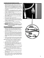
Locate the correct capillary tubes from the parts kit. Remove the
6.
2 - 1/4"OD tubes from the upper Y-connector. Insert the capillary
tubes into each line and re-assemble to the Y-connector.
note:
In some cases, the capillary tube requires trimming. Use a
SHARP utility knife to cut the tube cleanly without tearing or
crushing the tube.
Remove Reject Needle valve assembly and reconnect 3/8" tube.
7.
Plug-in power cord. Allow system to run and fill tank. This will
take 5-10 minutes.
Refer to Table 2 again. Under the column labeled “Flush Time in
8.
Seconds”, find the value that corresponds to the Raw Water TDS.
Enter this value in the controller under “FLUSH TIME X1”. Adjust
“FLUSH INT X2” to 1.5 Hours.
figure 5.
RO Reject Flow Control Assembly
TUBE
FLOW
CONTROL
Capillary
Not Trimmed
TUBE
FLOW
CONTROL
Capillary
Trimmed


