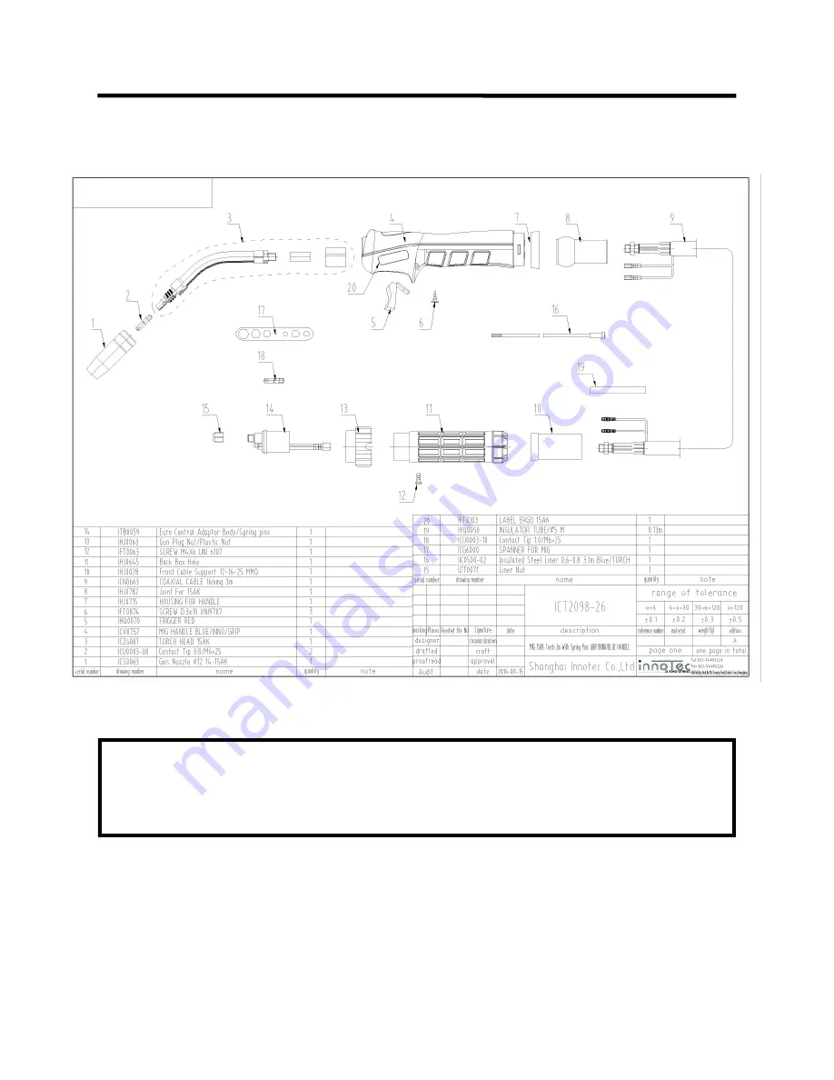
background image

54


15 SERIES MIG TORCH


Expanded  View


NOTE

:  Some components may appear slightly different as design/supplier changes are made from time to time.  At 

time of publication, the standard MIG gun provided with Power MTS is commonly known as the 15 Series. The Innotec® listed 

above is currently the default supplier of the 15 series.  Everlast is not the torch manufacturer, but equips the PowerMTS units 

with some of  the most proven torches in history.  Numerous manufacturers all over the world use interchangeable variations of 

these torches including Binzel and Trafimet. Most consumables and parts are interchangeable with other manufacturer

s guns 

designated as a 

“15”. 

The widely used Euro

-

connecter on the MIG torch also ensures that the customer can fit and install almost 

any other type MIG torch if they desire, since most manufacturers offer torches with a Euro connector as an option.  


Basic Theory and Function


Section 3


Summary of Contents for POWER MTS 211Si

Page 1: ...pecifications and Accessories subject to change without notice 329 Littlefield Ave South San Francisco CA 94080 USA Operator s Manual for the PowerMTS 211Si Safety Setup and General Use Guide A Digita...

Page 2: ...ns Installing The Wire Spool Front View Main Panel Front Panel Item Description and Explanation Side View Side View Item Description and Explanation Rear View Back Panel Rear Panel Item Description an...

Page 3: ...teract with each other Tech nical advisors are active on the forum daily We also divide our support into two divisions technical and welding performance Should you have an issue or question concerning...

Page 4: ...rums index php Main toll free number 1 877 755 WELD 9353 9am 5pm PST M F 11am 4pm PST Sat FAX 1 650 588 8817 Everlast Canada Everlast consumer satisfaction email sales everlastwelders ca Everlast Webs...

Page 5: ...roughly familiar with its safe and proper operation If you feel you need more information please contact Everlast The warranty does not cover improper use maintenance or consumables Accessories such a...

Page 6: ...damage unprotected eyes Always wear hearing protection because welding and cutting can be extremely noisy Ear protec tion is necessary to prevent hearing loss Even prolonged low levels of noise has be...

Page 7: ...y burning of the eyes nose or throat are signs that you need to increase ventilation Stop immediately and relocate work if necessary until adequate ventilation is obtained Stop work completely and see...

Page 8: ...all combustible materials including rags and spare clothing away from area Keep all flammable fuels and liquids stored separately from work area Visually inspect work area when job is completed for t...

Page 9: ...Amps MIG 0 1 Second TIG 0 10 Seconds Synergic MIG Synergic MIG function for wires from 023 to 045 in diameter with mild steel stainless and Alumi num settings Synergic feature operates via speed cont...

Page 10: ...been turned off and unplugged for 30 minutes to discharge the capacitors and to prevent the possibility of electrocution Do not grind or direct sparks near the welder to prevent damage to the panel fa...

Page 11: ...rs As already mentioned the welder is also spool gun spool gun optional ready for economical welding of Stainless and Aluminum wires if needed The spool gun will function in all MIG modes and is a goo...

Page 12: ...gun is limited to 4 rolls usually holding 1 lb of aluminum and 2 lbs of other filler metals so numerous spools may be needed on larger projects Basic Design and Construction This multi process welder...

Page 13: ...may continue to feed with out output Overcurrent events can be caused by too low of supply voltage running on undersized extension cords too large of welding wire diameter too high of settings for wi...

Page 14: ...he wire feed er s polarity located under the access cover GUN WORK CONNECT TO 5 8 CGA GAS FITTING AT REAR STICK WORK TORCH Spool gun is an optional item that may be pur chased separately from Everlast...

Page 15: ...a generally useable volt amp ratio for you After this is set based off of the inputs you have provided for wire diameter and wire type it is a simple matter of turn ing the amps up or down until the...

Page 16: ...ckness for aluminum Less is required for DC TUNGSTEN SELECTION GUIDE FOR AN INVERTER TYPE PERCENT COLOR PROCESS RECOMMENDATION Pure 100 Tungsten Green AC NOT RECOMMENDED Do not use in an in verter Int...

Page 17: ...le markings on tensioner handle for future reference 7 Remove the contact tip from the torch Not Shown Hold the torch cable and gun as straight as possible in direct line with the unit so feeding of t...

Page 18: ...18 FRONT VIEW MAIN PANEL POWER i MIG 211Si Setup Guide and Component Identification Section 2 15 16 6 2 1 14 11 8 4 10 3 9 13 7 12 5 17 18 19...

Page 19: ...it is switched off as the capacitors dis charge This is part of normal operation and not a defect 5 LED Stop Indicator This indicator will light up anytime a machine fault or an electrical issue is de...

Page 20: ...age while welding You will not be able to adjust amps wire speed on the panel in synergic mode since wire speed amp control is routed through the gun but will still be able to fine tune voltage on the...

Page 21: ...G Stick welders in this class It is more primitive but does a good job when HF start is not required or is restricted in HF sensitive envi ronments such as hospitals near electronic equip ment 11 Stic...

Page 22: ...utton and it will automatically spring back and return to adjusting in smaller increments 15 Euro Quick Connect for MIG Gun This style of connection makes the PowerMTS compatible with many after marke...

Page 23: ...gardless of brand without an adjustable arc force do have some fixed level of inductance though not all are set at the same level A user can either adjust the induct ance to have a familiar feel or to...

Page 24: ...he maximum set amps to the mini mum arc termination amps End amps where the arc is terminated is factory pre set and non adjustable For MIG operation the up and down slope functions are similar in con...

Page 25: ...s not adjustable in TIG or Stick mode In these processes Voltage is controlled by arc length Heat generated by voltage in stick mode can be managed through consistent feeding of the rod into the puddl...

Page 26: ...26 SIDE VIEW POWER MTS 211Si 4 5 3 1 2 Setup Guide and Component Identification Section 2...

Page 27: ...arity change if using flux core If the buss bar is con nected to negative then the work clamp should be in the positive output terminal Standard polarity for MIG is DCEP with the work clamp in the neg...

Page 28: ...28 REAR VIEW BACK PANEL POWERMTS 211Si Setup Guide and Component Identification Section 2 1x120 220V 1 2 3 FUSE 4 5 6...

Page 29: ...ug is the NEMA 6 50P This is the standard plug for welders operating on 240V in the US and Canada Other countries will have different configurations When oper ating on 120V use the adapter provided Do...

Page 30: ...ing to the sound of the arc A crisp steady sound frequently referred to as a Bacon frying sound should be heard The actual frying sound can vary somewhat and may have somewhat of a high pitch whine to...

Page 31: ...prove the low amp weld ing characteristics of the wire diameter For the best possible experience welding with the PowerMTS welder adjust the arc force after the wire speed and voltage have been tuned...

Page 32: ...he gun nozzle should be posi tioned directly over the weld without angling the wire to one side or the other of the weld as already mentioned The gun should have no more than 15 degrees lean pointed i...

Page 33: ...amounts of rust and mill scale These deoxidizers will float out most moderate amounts of contaminates out of the weld and will appear in the usual form of glassy like deposits on top of the cooled met...

Page 34: ...lain open root can be used as a backer plate adds to the time and labor involved A knife edge is also acceptable so long as the joint is fully penetrated when the weld is completed Open root gaps with...

Page 35: ...at on both sides of the joint and keeps the bead centered Don t confuse this with push or pull angle in the travel direction Correct Technique The gun is angled toward the back of the weld when travel...

Page 36: ...ge and amperage slow down to fill joint more Use push technique Characteristics Large convex weld with bulging at toes weld legs exceed thickness of the metal being welded Possible Causes Not enough v...

Page 37: ...37 MIG OPERATION Metal Thickness Wire Diameter Wire Speed Amps Inductance PGM MIG Work Sheet 1 Metal Type_________ NOTES Basic Theory and Function Section 3...

Page 38: ...38 MIG OPERATION Metal Thickness Wire Diameter Wire Speed Amps Inductance PGM MIG Work Sheet 2 Metal Type_________ NOTES Basic Theory and Function Section 3...

Page 39: ...39 MIG OPERATION Metal Thickness Wire Diameter Wire Speed Amps Inductance PGM MIG Work Sheet 3 Metal Type_________ NOTES Basic Theory and Function Section 3...

Page 40: ...40 MIG OPERATION Metal Thickness Wire Diameter Wire Speed Amps Inductance PGM MIG Work Sheet 4 Metal Type_________ NOTES Basic Theory and Function Section 3...

Page 41: ...41 MIG OPERATION Metal Thickness Wire Diameter Wire Speed Amps Inductance PGM MIG Work Sheet 5 Metal Type_________ NOTES Basic Theory and Function Section 3...

Page 42: ...42 MIG OPERATION Metal Thickness Wire Diameter Wire Speed Amps Inductance PGM MIG Work Sheet 6 Metal Type_________ NOTES Basic Theory and Function Section 3...

Page 43: ...he arc force for cellulose based flux welding rods is helpful Lowering the Arc force setting is generally desirable for rods iron powder Titania based flux Too much arc force will create overheating o...

Page 44: ...ther less Ar gon rich blends are sometimes recom mended and it is possible But when more CO2 is added the rust resistance of stainless goes down due to the added car bon content Ideally there are seve...

Page 45: ...upply a Flux core gun with a Euro connect fitting and will work Part time or occasional Flux core use with the standard MIG gun is acceptable as long as the nozzle is kept free of spatter 5 When runni...

Page 46: ...while welding at full selected val ue MIG Volts TIG Amps no finger con tact with the switch is required Following the graphic lines below you can visually trace the activity and function of each part...

Page 47: ...arc starting and tung sten preparation Welding If you are new to TIG welding it s important that you understand that TIG weld ing is much slower than MIG or Stick welding It requires patience and ste...

Page 48: ...erformed correctly If you cannot see the puddle or your helmet flashes auto darkening types you need to change your settings Practice feeding the filler wire without actually welding Manipulating the...

Page 49: ...torch switch or press the foot pedal Wait for the Pre flow to start Make sure pre flow is set for less than 4 seconds or start will be noticeably delayed 2 Quickly rotate cup so that the tungsten com...

Page 50: ...owly without much pressure 4 Rotate the Tungsten quickly as it is being ground to keep the point even and symmetrical Do not grind the Tungsten parallel to wheel face or an unstable arc will result Us...

Page 51: ...asic Theory and Function Section 3 TIG OPERATION Metal Thickness Tungsten Size Type Filler Diameter Gas Flow Rate Type Welding Amps Pulse Time On If Applicable PGM TIG Work Sheet 1 Metal Type_______ N...

Page 52: ...asic Theory and Function Section 3 TIG OPERATION Metal Thickness Tungsten Size Type Filler Diameter Gas Flow Rate Type Welding Amps Pulse Time On If Applicable PGM TIG Work Sheet 2 Metal Type_______ N...

Page 53: ...asic Theory and Function Section 3 TIG OPERATION Metal Thickness Tungsten Size Type Filler Diameter Gas Flow Rate Type Welding Amps Pulse Time On If Applicable PGM TIG Work Sheet 3 Metal Type_______ N...

Page 54: ...urer but equips the PowerMTS units with some of the most proven torches in history Numerous manufacturers all over the world use interchangeable variations of these torches including Binzel and Trafim...

Page 55: ...1 6 Collet Holder 1 7 Ceramic Cup 5 6 or 7 1 8 Tungsten customer supplied 0 9 Torch Cable 1 10 Torch Handle 1 11 Torch Switch 1 12 Torch Switch Connector 1 13 9mm 1 8 b quick connect coupling male 1...

Page 56: ...air or Replace it Control board damaged Check the circuit 9 Intermittent Arc Wandering arc Work Clamp is not secure or it is damaged Too windy breezy Check and or Work Clamp change position of clamp a...

Page 57: ...me Reduce stick out to less than 1 4 Increase cup size or use gas lens Clean metal thoroughly with approved metal cleaner or use acetone and a rag to clean metal Low flow rate of shielding gas High fl...

Page 58: ...ng E02 Over Current Operating machine on too small of a conductor Internal machine fault E04 Over Temperature Duty Cycle exceeded Blocked cooling Fans not operating properly E05 Stuck Switch Gun switc...

Page 59: ...59...

Reviews:

Related manuals for POWER MTS 211Si