Everlast Cyclone 212 Operator'S Manual Download Page 14

14


Setup Guide


Getting Started 

UNPACK YOUR UNIT. 

Upon arrival, you will need to completely unpack your unit, and check 

things over. This is a time sensitive matter. Do not delay or hold the 

welder unopened in the box. First, make sure the unit is opened from 

the top.  Be careful with using knives and sharp objects so you won

cut cords and cables inside the boxes.  Lay all items out and inspect 

them.  


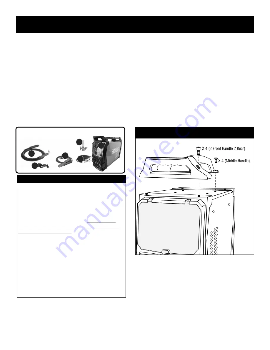
You should have the following in your box:


1.


Cyclone 212 MIG/Stick welder (bare unit).


2.


Floating Ball Regulator for MIG. (hose included but not pictured).


3.


15 Series MIG Gun/Torch. (MB15AK style)


4.


250A Work Clamp (approx. 9.5 ft with cable).


5.


250A Stick Electrode Holder (approx. 9.5 ft with cable).


6. 

240V to 120V power cord adapter.


INSPECT AND ASSEMBLE YOUR UNIT. 

When you receive your package, inspect the unit for damage. Check for 

the presence and general condition of the accessories. Some slight 

rubbing or chaffing of some of the accessories may be present, but this 

is considered normal. Most notably, the MIG torch may appear to be 

NOTICE:


This unit includes an additional 

.030” 

MIG contact Tip (it may also 

include a 

.023” 

but may vary by region) but does not contain any 

other MIG consumables, including filler (MIG or Flux

-

Cored) wire.  

Additional sizes of contact tips, nozzles and basic gun parts are 
available direct from Everlast

s website, from other online sources 

and may be also available locally at welding supply stores that carry 
parts for similar MB15AK styled MIG guns.  

Additionally, some 

miscellaneous parts like a contact tip wrench may be found in the 
box, depending upon your region.

  Filler (MIG and Flux

-

Cored) 

wire should be purchased locally or direct from other online 
sources. Other drive roll sizes and types should be purchased direct 
from Everlast.  The included drive roll is a V groove drive roll, de-
signed for solid steel wire 

.035” 

and 

.030” 

wire.  For flux core or 

aluminum use, you must purchase the correct type for proper wire 
feeding. See more drive roll information found later in this manual.


NOTE:  If you think you are missing a needed part, check the con-
sumable kit bag and box before calling Everlast for replacement.  If 
you are missing parts, call 1

-

877

-

755

-

9353 ext. 206 for help. (Only 

in the USA, for other areas, contact the distributor in your region).


used or fired. This is because it has been live tested in the factory for 

proper operation before putting into the box. If any item is damaged or 

missing, please inform Everlast within 72 hours of product receipt. See 

pages 4 and 5 for more details. Assemble the front, middle and rear 

handles with the supplied screws. Use a 5mm hex key to tighten the 

socket head cap screws to the front and rear handles.  (Screws may be 

found in the consumable bag.) Remove the cap screws from the center 

of the machine and install the center, long handle. Use a Phillips type 

screw driver to tight the screws, or alternately use a 10mm socket and 

1/4” 

drive socket wrench to tighten the screws.  IMPORTANT! Do not 

overtighten the screws.  

If desired for proper fitment or for space saving, 

the unit may be used without the handles.  However, install the screws 

and tighten them to the panels anyway.  Do not leave them out. Be sure 

to reinstall the handles if the unit is to be carried or lifted.  Do not lift 

from any other point on the machine or damage may occur.


POWER UP AND TEST YOUR UNIT. 

You will need to fully test the unit as soon as possible. Within 72 hours 

after receipt of the unit, be sure to have every thing you need at hand to 

test the unit.  Make sure the correct input power, wiring, and plug con-

figuration is being used.  Make sure you have the regulator is installed 

(See following section). Then, power up your machine without any ac-

cessories installed.  Allow the unit to idle for 15 minutes. Check and 

observe operation of knobs, controls and buttons, cycling through each 

as required. Make sure the fan is running at full speed.   After the static 

running test is completed, turn the unit off, connect the torches and 

cables. Then, conduct live testing of all the functions and features of the 

machine. For testing make sure work clamp is connected directly to the 

part being welded (work).  Check for arc starting and stability.  If you are 

testing the unit on 120V, maximum output will be reduced.  If any weld-

1


2


5


3


6


Cyclone 212


4


ASSEMBLE THE HANDLES


Summary of Contents for Cyclone 212

Page 1: ...USA North America Everlast Power Equipment 120 240V Welders Plasma Cutters Multi Process Safety Setup and General Use Guide For The Cyclone 212 FUNCTION MIG Stick Welder PURCHASE DATE MODEL NAME SERI...

Page 2: ...IT AND INSPECTION 14 CONNECTING YOUR UNIT TO THE POWER SOURCE AND WIRING INFORMATION 15 SHIELDING GAS CONNECTION AND SELECTION 16 SELECTING POLARITY AND INSTALLING TORCHES 17 INSTALLING THE MIG WIRE A...

Page 3: ...sation or business by any Everlast employee or subsidiary The owner of this product assumes all liability for its use and maintenance Everlast Power Equipment INC does not warrant this product or this...

Page 4: ...s unit to work as soon as possible Any issue should be reported within 48 hours 72 if on the weekend or holiday Everlast will not be liable for any shipping after that time What to do within the next...

Page 5: ...cessories are covered by a separate warranty and detailed infor mation can also be found at the link above Canada Customers Only For full details on the 3 year parts and labor warranty terms of sale a...

Page 6: ...use this machine until proper training has been received While accidents are never planned preventing an accident requires careful planning Stay alert Please carefully read this manual before you ope...

Page 7: ...reinforced or steel toe leather shoes and long sleeved flame resistant clothing i e denim Do not wear Poly Nylon blend materials DANGER Welding cutting poses shock and electrocution risks Keep this we...

Page 8: ...s vapor are harmful and can lead to organ failure and death If degreasing of a part is necessary use Acetone or an approved pre weld cleaner Use the proper personal protec tive equipment PPE when hand...

Page 9: ...Minimize direct skin and eye exposure to this intense form of radiation by using proper PPE and sun screen where appropriate CAUTION Do not allow bystanders Do not allow others without proper Personal...

Page 10: ...ed in For best practice do not start or stop the generator with this unit plugged in even if it is turned off Unplug the unit before shutting down the generator If using with a welder generator make s...

Page 11: ...mponents of the welder If the operating temperature of the unit is exceeded welding output will stop and an over temperature warning light error code will be displayed on the panel If a duty cycle eve...

Page 12: ...energy Additionally all cords and welding leads should be twisted together and run directly to the work without coils or excess cabling Normally this will not be required but it is supplied in the ca...

Page 13: ...s drops as well Regardless the duty cycle is not controlled by a timer Rather a heat sensor located on a heat sink near the critical power components of the welder signals overheat If the operating te...

Page 14: ...part check the con sumable kit bag and box before calling Everlast for replacement If you are missing parts call 1 877 755 9353 ext 206 for help Only in the USA for other areas contact the distributo...

Page 15: ...6 50 Plug to the NEMA 5 15 Plug to allow the unit to be used with 120V input without further modification of the welder No wiring or buss bar changes are required Once the unit is plugged in it will...

Page 16: ...nge throughout the industry However in the industry this unit is designed to be used with 98 2 Ar CO2 blend when welding Stainless Steel While there are other gas choices such as TriMix this is typica...

Page 17: ...ss or something similar Regard less the top terminal is positive and the bottom terminal is negative For MIG the wire feeder cable should be connected to the top positive ter minal with via the provid...

Page 18: ...G welding to prevent accidental arc striking and damage Remove the MIG torch while stick welding for the same reason The stick and MIG torch terminals will remain live despite the mode that has been s...

Page 19: ...transfer For upper range use and materials 3 16 and over 035 is advisable Remember if you change wire size or type you will need to either flip the lower drive roll over or completely change the drive...

Page 20: ...wire you will generally tension to at least 4 on the dial For flux cored wire it may be only two or three Wire diameter also plays a small part in the amount of required ten sion that is needed Regar...

Page 21: ...mains vacant For Flux Cored connect the work clamp For Plasma connect the work clamp 4 Control Connector For Plasma the torch switch wire connects here For the Spool Gun the control circuit wire goes...

Page 22: ...t off switch Other regions may vary and may have a different plug type or no plug at all Use the sup plied adapter to convert to 120V operation 3 HF Ground Service Bolt For use in a combined effort to...

Page 23: ...ust The actual direction may go either up and down or left and right depending upon the function level you are adjusting or selecting 7 Right Side Navigation Use the up and down arrow keys to navigate...

Page 24: ...letely through the left or right side functions and parame ters you will eventually cycle back to the default parameter area voltage wire speed amperage etc and the numbers will brighten to indicate t...

Page 25: ...Minute IPM and in Meters Per Minute m Min This is the default setting for the right side After 5 seconds of no input When the Wire Feed Speed is selected for adjustment the display will brighten in co...

Page 26: ...the need for constant trimming of the wire before restarting Use a setting of 1 to 3 seconds to begin with for most applications Smaller diameter wires need less burn back time Use the left Up and Dow...

Page 27: ...ng It offsets the drop in voltage by injecting extra amps into the weld when voltage drops below 20V This enables the amperage to react aggressively or mildly depending upon set tings to prevent arc o...

Page 28: ...ill activate the Pow erSet Screen for the process you are using Each process allows the use of PowerSet Once activated you will be ready to begin entering the information you need Using PowerSet Mode...

Page 29: ...e on a black background and display either AUTO or N A above them These will be blocked from access and will be automatically set for you If you desire con trol of these settings then deselect the Pow...

Page 30: ...ch whine to it If these sounds are present look at the arc to see if it is steady and producing low amounts of spatter If large amounts of spatter are present the puddle seems fluid appears wet and th...

Page 31: ...e used depending upon the application Weaves are employed for a number of reasons Weaves are often considered to have a more pleasing appearance and can help bridge gaps where fit up is a problem A we...

Page 32: ...ner metal gauges consider using one of these groove joints for best welding results When grinding or cutting the bevels especially with a single V groove it may be beneficial to leave a small land wit...

Page 33: ...ance of 5 degrees or less is acceptable from side to side The purpose is to prevent the arc from being concentrated on one side of the weld joint or the other This balances the heat on both sides of t...

Page 34: ...34 Component Identification and Explanation INNOTEC 15 SERIES MIG TORCH PARTS BREAKDOWN MB15AK Style...

Page 35: ...80 for best results The arc force control setting will vary from person to per son as well with different rod angles positions and arc lengths all factoring into the arc force control performance If...

Page 36: ...tart by set ting Hot Start to somewhere between 30 and 50 and set hot start time to 5 1 seconds Adjust in increments of 5 up or down to obtain best starting results When welding the weld will be slowe...

Page 37: ...d or broken fan Damaged Sensor Allow to cool for 15 minutes while switched on even if code disappears Check Fans Fans should run continuously Contact Everlast Tech Support Contact Everlast Tech Suppor...

Page 38: ...a rag to clean metal 6 Weld quality is poor Weld is dirty oxidized or porous Drafty conditions The welder is located on the workpiece and is blowing gas off due to fan activity Solenoid is sticking Fo...

Reviews: