EMV401/801/1601
4
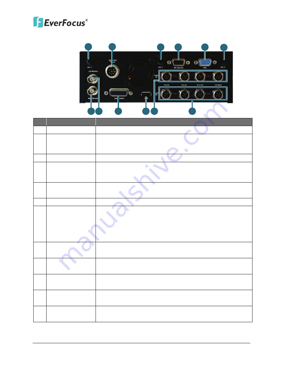
Rear Panel
7
10
9
11
12
8
1
2
3
4
5
6
No. Name
Description
1
Antenna 1 (3G/4G) Connects to the 3G or 4G Receiver for using 3G / 4G LTE function.
2
DC Power Input
Power harness cable for connecting to 12 VDC ~ 24 VDC power
source. For details, please refer to
2.4.1 Power Harness Cable
of
the User’s Manual.
3
Antenna 2 (GPS)
Connects to the GPS Receiver for using GPS function.
4
RS-232/485
Connects to RS-232 (CAN bus) or RS-485 device (such as analog PTZ
cameras), please refer to
2.4.5 RS-232 / RS-485 cable
of the User’s
Manual.
5
Main Monitor
(VGA)
VGA video output for connecting to the main monitor for live view,
playback and displaying OSD.
6
Antenna 3 (Wi-Fi)
Connects to the Wi-Fi antenna for using Wi-Fi function.
7
Main Monitor
(BNC)
BNC video output for connecting to the main monitor for live view,
playback and displaying OSD.
Note this mobile DVR has 3 Main Monitor outputs (one on the
front panel and the other 2 on the rear panel). All of the Main
Monitor ports can be connected simultaneously.
8
Call Monitor
(BNC)
BNC video output for connecting to the call monitor for displaying
the live view.
9
Alarm In / Out
D-Sub connector for connecting to the supplied Alarm Cable. For
details, please refer to
2.4.4 Alarm Cable
of the User’s Manual.
10 USB2.0 Port
USB2.0 ports for connecting to the 3G USB dongle, USB storage
device or mouse.
11 Video Input
M12 connector for connecting to the supplied Video Cable. For
details, please refer to
2.4.2 Video Cable
of the User’s Manual.
12 Audio Input
M12 connector for connecting to the supplied Audio Cable. For
details, please refer to
2.4.3 Audio Cable
of the User’s Manual.


