


EFN Series Fisheye IP Camera
22
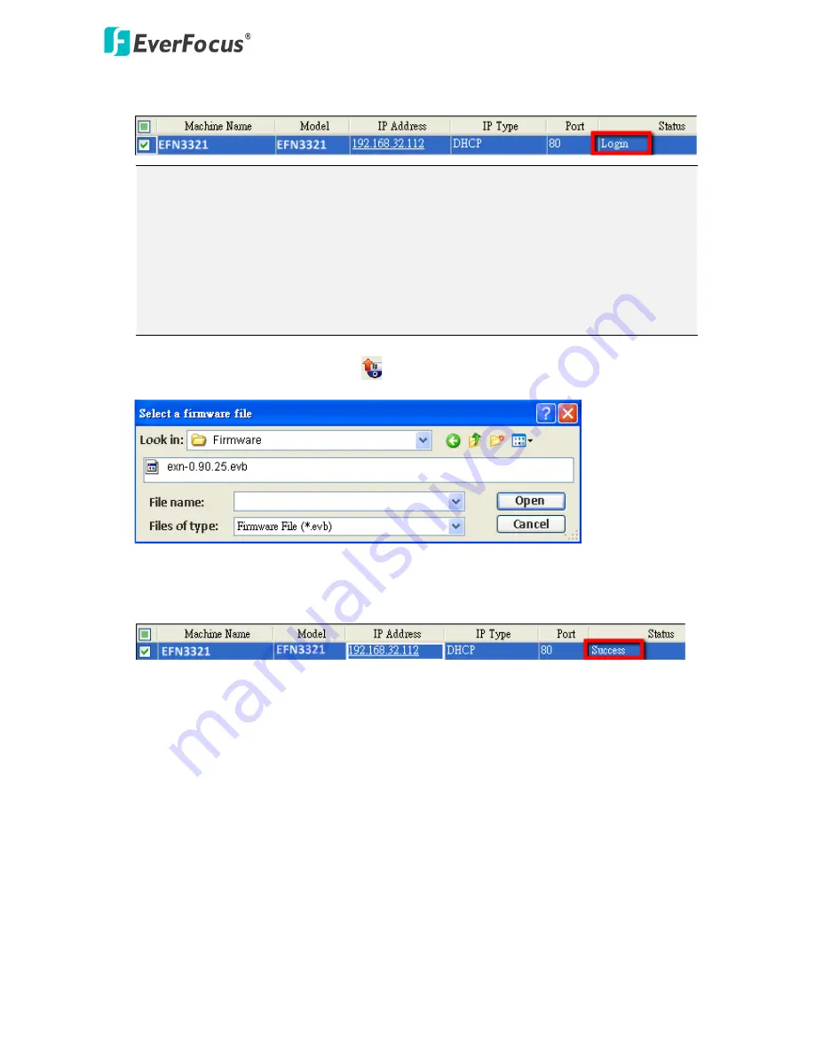
3.
Type the Username and Password. Click the
OK
button, the
Login
status displays.
Note:
1.
The default user ID is
user1
and the default password is
11111111
.
2.
If you select more than one camera that has the same user ID / password, you will be
able to log in several cameras at once.
3.
Up to 10 cameras can be simultaneously upgraded to the latest firmware. If you
connect the cameras to a PoE switch, please make sure the Power Consumption of
the PoE switch is sufficient.
4.
Click the
Upgrade Firmware
button
, a browsing window appears.
5.
Select the
firmware file (.evb)
and then click
Open
. The IPU will automatically upgrade the
firmware. The camera will reboot once the upgrade process is complete.


