EverFocus EFN3321 Quick Installation Manual Download Page 19


EFN Series Fisheye IP Camera   


18 

Note:   

1.


You might be required to install some add-ons for viewing the camera feed. If asked, 
click 

Run Add-on

2.


To enable Remove Live View, Firmware Upgrade and ActiveX Prompt on Internet 
Explorer, some settings have to be complete. Please refer to 

4.2 Settings for Microsoft 

Internet Explorer

 in the 

User’s Manual.


2.


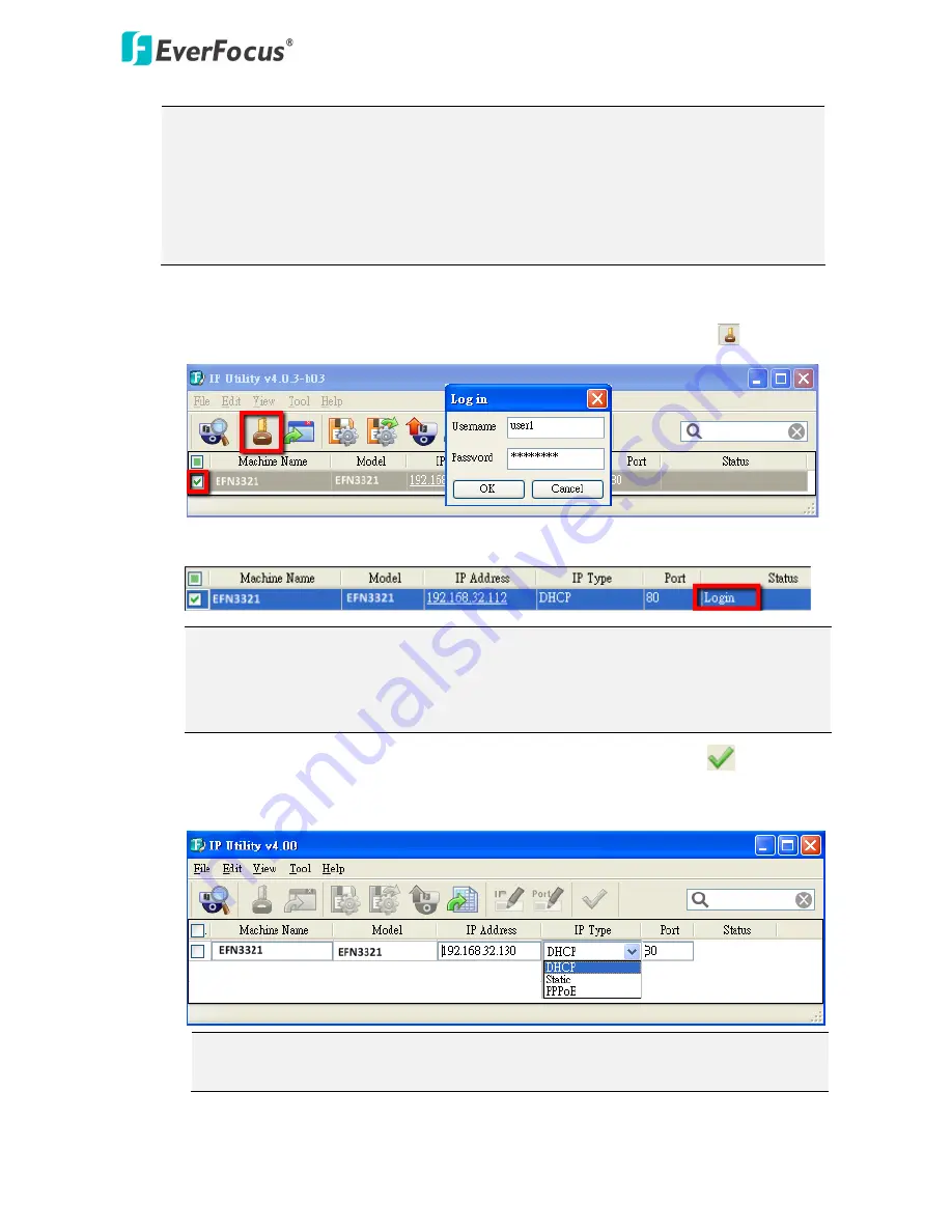
To optionally configure the Machine Name, IP Address, IP Type or Port Number using the IPU: 

a.


Log in the camera by checking the desired model and then click the

 Log in


  icon.   


b.


Type the Username and Password. Click the 

OK 

button, the 

Login

 status displays. 


Note:


1.


The default user ID is 

user1

 and the default password is 

11111111

.


2.


If you select more than one camera that has the same user ID / password, you will 
be able to log in several cameras at once.


c.


Right click the column to configure the settings. Click the 

Apply Changes


  button to 

apply and save the settings. 


Note:

  Most networks uses DHCP to assign IP address, if you are unsure of your 

network settings, please consult your network administrators for configuration details.


Summary of Contents for EFN3321

Page 1: ...EFN Series Fisheye Network Camera 3MP 360 ePanoramic View IP68 IK10 Quick Installation Guide Indoor Outdoor Copyright EverFocus Electronics Corp Release Date August 2014...

Page 2: ...320 3 MP Indoor Yes EFN3320 3 MP Indoor Yes Yes Yes Yes EFN3321 3 MP Outdoor IP68 IK10 Yes Yes Yes Yes Indoor Type 2 1 3 Rear View Front View No Item Name Descriptions 1 Reset Button Press the button...

Page 3: ...n the cable conduits for waterproofing 3 Reset Button Resets all configurations to the factory default settings Press and hold the Reset Button for 10 seconds by using a pen or a paper click 4 Micro S...

Page 4: ...nstallation Guide x 1 Outdoor Type Camera x 1 Desiccant Bag x 2 Base Plate Screw x 4 Inner Paper x 1 Screw Anchor x 4 Software CD x 1 Hexagon Screwdriver x 1 Quick Installation Guide x 1 Note 1 Equipm...

Page 5: ...lso speakers microphones with a built in amplifier and external power supply are required Alarm Input Output Audio Input TRS Line in Pink Audio Output TRS Line out Green Video Test Out BNC 12 VDC Inpu...

Page 6: ...are required 1 2 3 4 5 6 7 8 9 10 11 12 Camera Module No Functions No Functions 1 12 VDC Input 7 Audio Input C TRS Line in 2 Digital GND 8 Audio GND 3 Alarm Out Alarm Output C 9 Audio Output TRS Line...

Page 7: ...l the three red cross marks on the inner circle and the square below only if you wish to run the cables through the ceiling desk Note that the square below also indicates the cable position Point the...

Page 8: ...sing the supplied three Screws Base Plate 3 Place the Spacer onto the rear side of the camera Remove the cut out from the Spacer only if you want to run the cables along the ceiling desk Spacer 4 Opti...

Page 9: ...te that the triangle mark on the rear side of the camera and the Base Plate should point to the same direction Rear side of the camera Base Plate 6 Connect the network or power cable to the camera The...

Page 10: ...sh to run the cables through the wall Note that the square below also indicates the cable position Point the square below to the direction for running the cables Drill a hole only if you want to run t...

Page 11: ...4 Optionally insert the micro SDHC SDXC card to the push pull type SD card slot on the rear side of the camera Push Pull Rear side of the camera 5 Align the three latches on the camera with the three...

Page 12: ...t Rear side of the camera Base Plate Tilting Wall Mount Bracket 6 Connect the network or power cable to the camera The installation is now complete 3 3 Outdoor Type The following instruction is an exa...

Page 13: ...crew the Base Plate to the ceiling wall desk using the supplied four screws Base Plate Wiring Box Wall If you want to wire the cables through the bottom of the Camera Case follow the steps below a Rem...

Page 14: ...om of the Camera Case Cable Gland Camera Case c Screw the Circle Plate to the side hole on the camera Case d Screw the Base Plate to the ceiling wall desk Base Plate Wall If you want to install the ca...

Page 15: ...e to be bundled into a cable with diameter ranging from 5 3mm to 6 4mm see Step d below Screw Body Screw Cap Stopper Claw Plug Stopper Adjustment Ring s Cable Gland Cable Gland Screw Cap a Keep the su...

Page 16: ...ted with one cable The Cable Conduit has been tested to support cable diameter between 5 3mm and 6 4mm Please refer to the image below to bundle the lose wires before inserting to the Cable Conduit e...

Page 17: ...icro SDHC SDHC card to the card slot 9 Stick the supplied 2 desiccant bags inside the camera case Note It is highly recommended to replace the desiccant bags every time when you open the camera 10 Pla...

Page 18: ...e following IPU window appears The IPU will automatically search the IP devices connected in the LAN Double click the IP address of the desired device the login window pops up Type the user ID and pas...

Page 19: ...a Log in the camera by checking the desired model and then click the Log in icon b Type the Username and Password Click the OK button the Login status displays Note 1 The default user ID is user1 and...

Page 20: ...IP Address for example 172 17 0 145 Please also set up the Subnet Mask and Gateway Click the Apply Changes button to apply and save the settings To show the Subnet Mask and Gateway items on the title...

Page 21: ...ction Please refer to 7 1 1 Network DDNS in the User s Manual Cat 5 Straight Through Cable High speed modem Internet Router or LAN Connection This is the most common connection in which the IP camera...

Page 22: ...PC has another network connection the IP camera will be the only network device visible to the PC See the diagram below Cat 5 Right Pinout of a crossed over cable 6 Upgrading Firmware You can upgrade...

Page 23: ...ou will be able to log in several cameras at once 3 Up to 10 cameras can be simultaneously upgraded to the latest firmware If you connect the cameras to a PoE switch please make sure the Power Consump...

Page 24: ...co jp info everfocus co jp EverFocus China Shanghai Room 403 Ruijin Business Center No 96 Zhaojiabang Road Luwan district Shanghai 200020 China TEL 86 21 6471 2229 6471 2291 FAX 86 21 6471 0566 www e...

Reviews: