


EFN Series Fisheye IP Camera
20
5.
Connecting to the Network
You can use one of the methods below to connect the camera to the network.
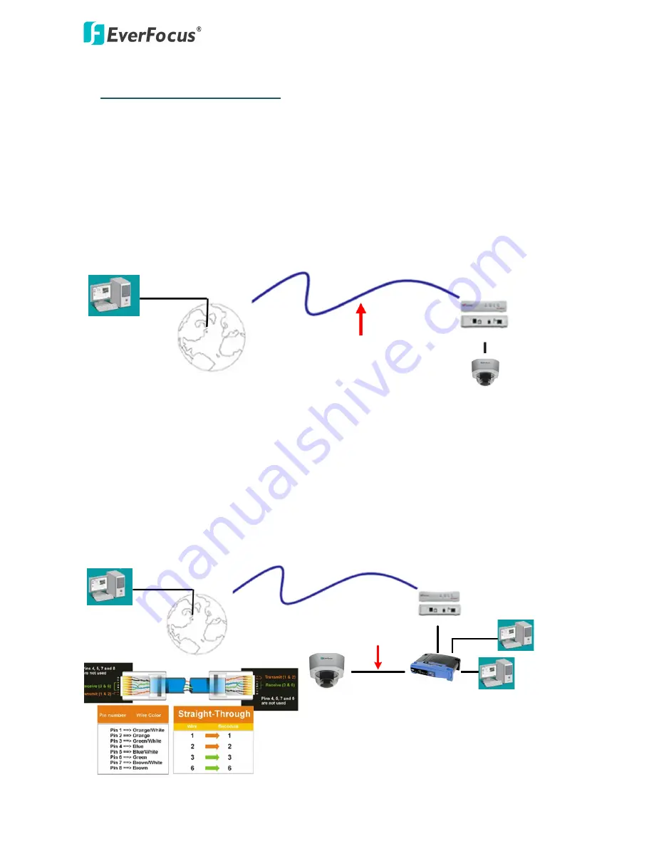
Direct High-Speed Connection
In a Direct High-Speed Connection, the camera connects directly to a modem without the need for a
router. You need to set the static or dynamic WAN IP address assigned by your ISP (Internet Service
Provider) in the camera’s configuration web pages. To access the camera, just type
“http://xxx.xxx.xxx.xxx”, where xxx.xxx.xxx.xxx is the IP address given by your ISP. If you have a
dynamic IP address, this connection may require that you use DDNS for a reliable connection.
Please refer to
7.1.1 Network (DDNS)
in the
User’s Manual
.
Cat 5
Straight Through Cable
High-speed modem
Internet
Router or LAN Connection
This is the
most common connection
in which the IP camera is connected to a router and allows
multiple users on and off site to see the IP camera on a LAN/WAN (Internet). The camera must be
assigned an IP address that is compatible with its LAN. By setting up port forwarding on the router,
you can remotely access the cameras from outside of the LAN via the Internet. To remotely access
the Web interface of the IP camera, please refer to
7.1.1 Network (DDNS)
in the
User’s Manual
. To
set up port forwarding, please consult the manual of the router.
High-speed modem
Internet
Straight-through LAN patch cable
Router
Cat 5 Straight Through Cable
Left: Pinout of a straight-through cable.


