


4 DTR Output
Data
terminal
ready
5
GND
----
Signal ground wire
6
DSR
Input
Data equipment ready
7
RTS
Output
Request for sending
8 CTS Input
Delete
sending
9 RI Input
Ring
test
3)
The EA-LAN1 DB9 pin definition for an RS485 corresponding pin is
below.
DB9 PIN #
RS232
RS485-Half
RS485-Full
RS422
1 DCD
N/A
N/A
RTS-
2 RXD
DATA-
TXD-
TXD-
3 TXD
DATA+
TXD+
TXD+
4 DTR
N/A
RXD+
RXD+
5 GND
GND
GND
GND
6 DSR
N/A
RXD-
RXD-
7 RTS
N/A
N/A
RTS+
8 CTS
N/A
N/A
CTS+
9 N/A
N/A
N/A
CTS-
4)
The RS485 connection must be matched with the device being used with the
server. In our case the device is the Main Module of the controller.
5)
Connect the DB9 of the EA-LAN1 to the Main Module as follows:
DB9
(Pin # - Pin Name)
RS485 on Main Module
(Pin # - Pin Name)
2 – RX
11 – RS485_B
3 – TX
10 – RS485_A
5 – GND
12 – GND
6)
The EA-LAN1 should now be properly connected to the controller.
Double check the connection, and verify that the power and the Ethernet
are both connected to the EA-LAN1.
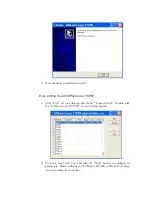
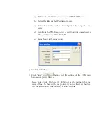
Installing the “COM Port Simulation” Driver on the
Admin PC
The COM Port over TCP/IP driver must be installed on the admin PC to allow
Windows to communicate with the EverAccess controller through the net. In this
chapter you will learn how to install this driver and be able to map it to the COM
ports available through the PC. The following two sections in this chapter help
explain:
•
How to Install COM Port over TCP/IP Driver


