


13)
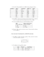
The EA-LAN1 pin definition for an RS232 corresponding pin is below.
DB9 PIN #
RS232
RS485-Half
RS485-Full
RS422
1 DCD
N/A
N/A
RTS-
2 RXD
DATA-
TXD-
TXD-
3 TXD
DATA+
TXD+
TXD+
4 DTR
N/A
RXD+
RXD+
5 GND
GND
GND
GND
6 DSR
N/A
RXD-
RXD-
7 RTS
N/A
N/A
RTS+
8 CTS
N/A
N/A
CTS+
9 N/A
N/A
N/A
CTS-
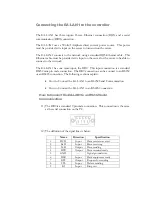
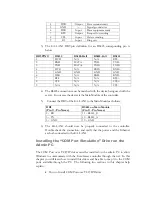
14)
The RS232 connection must be matched with the device being used with the
server. In our case the device is the Main Module of the controller.
15)
Connect the DB9 of the server to the Main Module as follows:
DB9
(Pin # - Pin Name)
RS232 on Main Module
(Pin # - Pin Name)
2 – RX
14 – TX
3 – TX
13 – RX
5 – GND
12 – GND
16)
That’s all. Make sure the connection is correct, the power and the Ethernet
are both plugged in.
How to Connect the EA-LAN1 to an RS485 Connection
1)
The DB9 is a standard 9 pin male connection. This connection is the same
as the serial connection on the PC.
2)
The definition of the signal lines is below.
Name
Direction
Specification
1
DCD
Input
Data carrier wave test
2 RxD Input
Data
receiving
3 TxD Output
Data
sending


