background image

EVC electronic GmbH

-6-

BSL100 Manual

BSL131 Programming Adapter

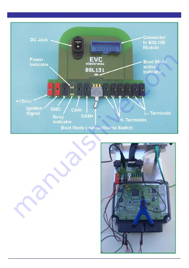
Pict 1: The BSL131 programming adapter en detail.

The BSL131 programming adapter is intended
for ECUs which do not have the typical BOSCH-
pad array or for ECUs which have more then one
"bootpin" must be configured.

Like on the BSL130 probe, the power distribution
of the ECU is controlled by the BSL100 module.

The connection to the power supply and to the
CAN bus are made to the main connector of the
ECU using the included cables and alligator
clips.

The connection to he "bootpins" are made using
additional orderable cables and probes. .

The switch on the BSL131 adapter the L- and H-
terminals can be switched to high impedance
state.

Pict.2: A Bosch MED17.5.5 is connected to a
BSL131 adapter.

ð

Summary of Contents for BSL100

Page 1: ...Manual BSL100 Bootstrap Loader Module for Infineon Tricore Microcontrollers ...

Page 2: ...le of Contents Theme Page Important 3 Disclaimer Warranty 3 The BSL100 Module 4 BSL130 Probe 5 BSL131 Programming Adapter 6 BSL132 Probe 7 BSL ADP 8 BSL DRV 9 BSL100 Manual 10 EVC electronic GmbH Am Pfauenzehnt 11a 46539 Dinslaken www evc de ...

Page 3: ...uously updated list of ECUs which can be programmed with the BSL tools can be found following this link http www evc de en product bsl ecu asp Disclaimer Warranty The BSL100 module is for use by qualified personnel only A warranty on our part for direct damages and consequential damages caused by the improper handling of our product or additional products is excluded To avoid damages on your BSL10...

Page 4: ...le The lower of the both blue LEDs on the front panel now starts flashing The BSL100 module has no own power source It is an USB device and obtains Its power via the USB cable If the BSL100 module is connected to an ECU the upper of the both blue LEDs indicates that a data transfer is in progress Pict 2 The BSL module is always connected to the USB cable first Pict 3 The BSL100 has etablished a da...

Page 5: ...the ECU The switching of the power is controlled by the BSL100 module A red LED on top of the BSL130 lights up indicating the ECU receives power Picture 2 shows the pin out of the 2 x 7 pad array Both the CAN bus lines and also the power for the ECU are routed from here The extra pads of this array are not used On Bosch ECUs the 2 x 7 pad array commonly is located near the border of the board Pict...

Page 6: ...Like on the BSL130 probe the power distribution of the ECU is controlled by the BSL100 module The connection to the power supply and to the CAN bus are made to the main connector of the ECU using the included cables and alligator clips The connection to he bootpins are made using additional orderable cables and probes The switch on the BSL131 adapter the L and H terminals can be switched to high i...

Page 7: ...0 probe the power to the ECU is controlled by the BSL100 module The BSL130 probe is shipped together with a12V power supply which powers the ECU Up to four cables connecting the bootpins to the corresponding 2 mm H and L Terminals of the BSL132 adap ter The switch toggles the H and L Terminals between CAN boot mode conducting and normal boot mode high impedance state Pict 2 The pin out of the 2 x ...

Page 8: ...he password can be read then First the GND connection needs to be estab lished In case of the BSL131 the included black cable can additionally be connected to the GND socket of the BSL131 In case of the BSL130 or BSL132 an extra GND connection to the ECU is required Using the red cables with the clamp type test probes each of the channels S1 and S2 need to be connected to the corresponding pin of ...

Page 9: ...laced Nevertheless for realizing a CAN bus connec tion the BSL DRV module is plugged onto a BSL131 or BSL132 probe On the other side the BSL module is connected to the 14 way flat ribbon cable of the BDM100 module By using two BSL MPST probe tips the TXD and RxD lines from the ECU are connected to the BSL DRV module Pict 2 Detailed view of the BSL DRV module In this case it s plugged to a BSL131 p...

Page 10: ...revision Publisher EVC electronic GmbH 46539 Dinslaken Author Matthias Billian Although we were afforded to describe all details with the highest possible precision nevertheless we can not guarantee an error free content of this manual EVC electronic GmbH Am Pfauenzehnt 11a 46539 Dinslaken www evc de ...

Reviews: