


Page 12
Vista 42 Indoor Gas Fireplace
rev. 110201
42”
42”Min. Rigid
46”Min Flex
B
C
A
Ve
rtical Run (in.)
Installation
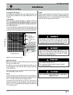
The Venting Graph: Vista 42
Measure the vertical height from the fireplace hearth to the center of the termination
and the horizontal run from the fireplace flue collar to the wall flange of the termination.
Plot on the Venting Graph
Figure 14
with an 'X'.
If the 'X' falls on or above the top boundary of the shaded area, the installation is
acceptable.
Example A: (Acceptable Installation)
If the vertical dimension from the hearth is 84" and the horizontal run to the wall
flange of the vent termination is 36" then the vent configuration is acceptable.
Example B: (Acceptable Installation)
If the vertical dimension from the hearth is 72" and the horizontal run to the wall
flange of the vent termination is 66" then the vent configuration is acceptable.
Example C: (Unacceptable Installation)
If the vertical dimension from the floor of the fireplace is 74" and the horizontal
run to the wall flange of the vent termination is 108" then the vent configuration
is
NOT acceptable.
Figure 14.
Vista 42 Top Vent
Venting Graph for
wall-mounted
terminations.
Section 3-3-1:
VENTING LAYOUT: Wall mounted termination.
Selection of components and details of venting layout must adhere to the
following:
Vent terminations must not be recessed in walls or siding.
All through-the-wall terminations within 36 horizontal inches and 46 vertical
inches of the fireplace
must
have a European Home RHS101 Heat Shield
installed. See
Section 3-3-3
.
All through-the-wall terminations beyond 36 horizontal inches and 46 vertical
inches of the fireplace
must
have either a European Home RHS8 Heat Shield
or a European Home RHS101 Heat Shield installed. See
Section 3-3-3
.
Once the proposed venting layout has been determined refer to
Figure 14
to ensure the layout is acceptable.
Notes Wall Mounted Terminations:
Top Vent
All measurements for vertical or horizontal runs are measured from center
of the vent pipe.
Venting runs
must
fall within the limits set by the venting graph, see
Figure 14
.
Wall mounted Terminations
The following details are some possible configurations for wall-mounted termina-
tions. See below.
Unacceptable vent run
within shaded area.
Acceptable vent runs
within unshaded area.
If your installation does not fall within
the venting graph parameters, please
contact European Home for power
venting options.
Figure 16.
Top Vented,
wall-mounted installation with1 elbow (1 one
90° bend).
The
vent run must comply with Venting Graph for
Top vent, wall-mounted
terminations,
Figure 14.
Figure 16a
.
Top Vented
, wall-mounted Multi-elbow installation.
See Venting Graph
for
Top vent, wall-mounted
terminations,
Figure 14.
RHS8 Heat
Shield
Termination
Hearth
Exterior
Wall
42”Min. Rigid
46”Min. Flex
42” Max.
Flex section
shown
Solid Section
Flex Section
Hearth
30”min
15’foot Max.
RHS8 Heat
Shield
Termination
Exterior
Wall
8’foot
Max.