Eurolube Equipment 15715 Service Manual Download Page 6

www.eurolube.com

EUROLUBE EQUIPMENT AB

PART NO 15715

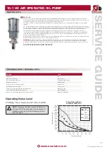
10:1 HV AIR OPERATED OIL PUMP

6


www.eurolube.com

33

31

30

31

32

31

30

34

25

25

15

21

23

24

20

25

25

23

24

Figure 2

Head Assembly

Assembly Stage 1 

Figure 3

Head Assembly

Assembly Stage 2 

G

G

L

G

L

G

L

25

- Item number

- Grease application point, see 

detail in written procedure

- Loctite application point, see 

detail in written procedure

L

L

Exploded


Views

Air Motor

Summary of Contents for 15715

Page 1: ... from thermal expansion A pump s ability to deliver grease is based on the pressure bar psi and quantity of air supplied to the air motor and the amount of material discharge back pressure to be overcome within the system Warning Do NOT use solvents or other explosive fluids An explosion can result in the pump when aluminium and zink parts come in contacts with certain solvents Never point a contr...

Page 2: ...OIL PUMP 2 Figure 12 Complete Pump Dimensions Features Ø 155 6 hole circle 45 2 17 Ø 11 5 4places equallyspaced 55 TYP 45 155 5 hole circle 11 5 4 places equally spaced 1 NPT F Fluid Inlet Port 3 4 NPT F Fluid Outlet Port 1 2 NPT F Air Inlet Port 78 264 654 127 67 91 152 292 ...

Page 3: ... scarring the pump surface Using a socket wrench hold the 1 2 Hex Acorn Nut 11 on the pump Cap 1 With a 6 second socket wrench loosen and remove the 1 2 Hex Nut 10 and Lock washer 9 at the other end of the 1 2 13 Threaded Stud 7 Then remove the Acorn Nut 11 and Stud 7 as a group Do not remove the Acorn Nut from the Threaded Stud Repeat the procedure for the other three Studs Set aside all fastener...

Page 4: ...hreads of the 5 16 Jam Nuts 25 and install on the stems 23 and tighten to 70 in lbs using two open end wrenches It will be necessary to secure the hex cap of the Valve Stem 23 with an open end wrench while securing the first nut Then install the O Ring Seals 24 into the gland of the two Valve Stems 23 FIGURE 3 Secure the Rod Head 33 in a bench vise clamping the part across the flats Apply 3 Loctit...

Page 5: ...31766 Spring 2 2 31 831767 Retainer Spring 3 3 Item PART NO DESCRIPTION QTY IN PUMP SERVICE KIT QTY 900020 900027 900028 32 831768 Trip Rod 1 1 33 831769 Rod Head 1 1 34 831770 Retainer Spring Threaded 1 1 35 830641 Label Eurolube 1 36 830350 Label Warning 1 37 832114 Lifting Eye 1 38 831823 Fluid Adapter Lion HP 10 1 1 39 831993 Foot Valve Seat Vented 1 40 806962 Ball 2 41 829769 Pin Footvalve 1 ...

Page 6: ... 32 31 30 34 25 25 15 21 23 24 20 25 25 23 24 Figure 2 Head Assembly Assembly Stage 1 Figure 3 Head Assembly Assembly Stage 2 G G L G L G L 25 Item number Grease application point see detail in written procedure Loctite application point see detail in written procedure L L Exploded Views Air Motor ...

Page 7: ...OIL PUMP 7 25 25 24 22 Figure 4 Head Assembly Assembly Stage 3 18 6 19 25 25 24 22 27 28 29 Exploded Views Air Motor G G G G G G L 25 Item number Grease application point see detail in written procedure Loctite application point see detail in written procedure L L 1 drop only ...

Page 8: ...P 8 11 8 2 9 10 9 10 26 5 11 8 7 9 10 8 11 Figure 5 Head Assembly Assembly Stage 4 5 G G G L 25 Item number Grease application point see detail in written procedure Loctite application point see detail in written procedure L 7 37 1 3 35 36 Label on Back Side Exploded Views Air Motor ...

Page 9: ...6 Figure 8 Bare Pump Assembly Assembly Stage 7 G L 25 Item number Grease application point see detail in written procedure Loctite application point see detail in written procedure 43 54 53 1 drop only L 1 drop only L 1 drop only L 1 drop only L 1 drop only L G G Exploded Views Lower Assembly Figure 6 Bare Pump Assembly Assembly Stage 5 Figure 7 Bare Pump Assembly Assembly Stage 6 50 40 48 47 49 4...

Page 10: ...sembly Assembly Stage 8 Figure 10 Bare Pump Assembly Assembly Stage 9 G G G L 25 Item number Grease application point see detail in written procedure Loctite application point see detail in written procedure 1 drop only L 45 58 59 60 61 G 44 38 43 45 46 38 50 48 Figure 8 Bare Pump Assembly Assembly Stage 7 Figure 9 Bare Pump Assembly Assembly Stage 8 G G ...

Page 11: ...drop only L 54 G L 25 Item number see page 10 Grease application point see detail in written procedure Loctite application point see detail in written procedure Exploded Views Lower Assembly Exploded Views Complete Pump Figure 11 Final Pump Assembly Assembly Stage 10 Complete Air Motor Subassembly 14 Complete Lower Pump Subassembly 52 13 12 16 17 ...

Page 12: ...io is 50 1 the theoretical fluid pressure will be 50 times to the air pressure when the pump stalls out The air is exhausted from the pump via a sound attenuator Installation Operation To achieve long pump life we recommend that filter regulator to be installed prior to the air inlet of the pump 1 Remove the protective packaging from the pump and also the protective plugs 2 Fit the 2 pump adaptor ...

Reviews: