


EUROLUBE EQUIPMENT AB
stråssavägen 2, sE-711 76 storå, sweden
PHONE
+46 581 836 65
FAX
+46 581 409 75
www.eurolube.com
PART NO 15715
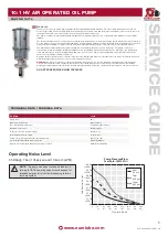
10:1 HV AIR OPERATED OIL PUMP
12
sYMPTOM
POssIBLE REAsON
sOLUTION
Pump does not operate
Inadequate air supply pressure or restricted air line
Clogged lines, hoses, valves, etc
Damaged air motor
Increase air line size or clean air supply
(1)
. Assure air is on and valves are open
Open; clear
(1)
Service / replace air motor
Air motor is not tripping over
Air motor seals are worn/damaged
Service / replace air motor / ensure a filter is used on air inlet to pump
Air is leaking from exhaust and/or seal dam-
age, etc
Air motor seals are worn/damaged
Service / replace air motor / ensure a filter is used on air inlet to pump
Fluid is leaking from the exhaust
Fluid seal [44, fig 8] is worn/damaged
Replace fluid seal
Erratic pump operation
Air entering suction line
Pressure relief valve is stuck
Fluid level too low
Air motor icing
Check for loose suction connections
Replace fluid piston
Refill, reprime or flush
Run pump at lower pressure, run at lower
cycles per minute; clean muffler [17]
Pump runs continously
Empty fluid supply
Blockage in pump tube in foot valve [39]
Lower ball [40] is stuck in foot valve [39]
Lower seal [49] is worn or damaged
Refill, reprime or flush
Remove pump tube, clear blockage
Replace ball and reseat foot valve
Replace
Pump operates slowly, and pump output on
both strokes is low
Inadequate air supply pressure or restricted air line
Closed or clogged dispensing valve
Air inlet strainer/filter clogged
Increase air supply; increase air supply size
Clear
(1)
Clear
(1)
Troubleshooting
The pump is intended for non-corrosive and petroleum based liquids. It may NOT be used for other
•
purposes or for pumping gasoline,
or other explosive liquids.
Check that all components used are suitable for the operating pressure of the system.
•
Do not use higher pressure than required for the satisfactory functioning of the system.
•
Before a system is put into operation it is recommended that the system be pressurized to 1,3 times max.
•
working pressure.
Before work is undertaken on the pump the compressed air should be disconnected from the pump and the
•
whole system
should then be depressurized.
Check all components thoroughly for damage and leakage.
•
Ensure that the compressed air is disconnected from the pump and the system is depressurized when
•
system is not in use i.e. overnight or during longer shut down periods as there is always a risk of hoses
bursting or pipework leaking etc.
General
The pump is made up of two main parts: A compressed air operated two way piston air motor and a double acting
liquid pump. The liquid is sucked into the pump tube via the bottom valve. When the piston moves upwards liquid
is forced out of the fluid outlet. The fluid is forced out of the pump when the piston is moving in both directions.
The relationship between the air piston and the pump piston determines the ratio of the pump. If the pump ratio
is 50:1 the theoretical fluid pressure will be 50 times to the air pressure, when the pump stalls out. The air is
exhausted from the pump via a sound attenuator.
installation/Operation
To achieve long pump life we recommend that filter regulator to be installed prior to the air inlet of the pump.
1.
Remove the protective packaging from the pump and also the protective plugs.
2.
Fit the 2” pump adaptor firmly on to the barrel.
3.
Mount the pump into the pump adaptor and lock into position.
4.
Fit and secure the outlet hose.
5.
Fit and secure the air inlet hose, slowly increase the air pressure letting the pump slowly build up fluid pres-
6.
sure.
Ensure there are no leaks either on the air inlet or at the fluid outlet. To obtain maximum vacuum all connec-
7.
tions should be sealed and tight.
Slowly increase the air pressure to optimum working pressure.
8.
Warning!
The maximum permitted air pressure is 10bar, do not exceed this limit. Service: Before any service-
work is carried out the compressed air must be turned off to the pump or the air coupling disconnected. And
the fluid outled must be depressurized completely.
Maintenance
Before any service work is carried out the compressed air must be turned off to the pump or the air coupling
1.
disconnected. And the fluid outlet must be depressurized completely.
Clean the air filter, remove all pollutants including condensed water.
2.
Check system for any air or fluid leaks.
3.
Always keep the equipment clean and remove foreign objects, ensure no pollutants enter the barrel as these
4.
will be pumped into the system.
When changing the barrel make sure the pump remains clean (Do not put on to floor otherwise the grease will
5.
become polluted).
When depressurizing the system or removing the outlet hose from the pump ensure there is a container avail-
6.
able to drain the excess grease into.
Service
For your personal safety ensure the air is disconnected from the pump, and the fluid discharge is depressur-
1.
ized before any service is carried out. Be cautious when repressurizing the system after any service work is
carried out.
During service procedures it is important to avoid any scratching or any other damage to gasket or bearings
2.
surfaces. Keep tools and benches clean. Be extremely cautious when assembling or dismantling V-packings
and O-rings. Exchange all worn or damaged parts no matter how slightly damaged they seem.
Clean and grease all gasket, bearing surfaces including O-rings and gaskets with teflon grease when reas-
3.
sembling pump.
Try to use paraffin to clean pump parts. If water based cleaners are used, wipe parts clean & dry immediately
4.
to avoid corrosion.
Eurolube Equipment AB, Stråssavägen 2, SE-71176 Storå, Sweden, declares hereby that the products:
Air operated oil pump, model: 15715 Are in conformity with the requirements of the Council´s Machinery Directive 2006/42/EC.
Storå September 3, 2012
(1) Follow the Pressure Relief Procedure and disconnect the fluid line. If the pump starts when the air is turned on again, the line, etc. is clogged.
DEcLARATION OF cONFORMITY
Morgan Gustavson,
Product director (Authorized representative for Eurolube Equipment AB and responsible for technical documentation).
PRODUcT sAFETY INsTRUcTIONs


