


www.eurolube.com
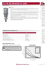
10:1 HV AIR OPERATED OIL PUMP
www.eurolube.com
EUROLUBE EQUIPMENT AB
PART NO 15715
10:1 HV AIR OPERATED OIL PUMP
5
ITEM
PART NO#
DEscRIPTION
QTY IN
PUMP
sERVIcE KIT
QTY
9
000
20
9
000
27
9
000
28
1
831791
Cap
1
2
831763
Upper Body
1
3
831793
Center Insert
1
4
831795
Lower Body
1
5
830695
Seal, O-Ring, -258
2
2
2
6
806909
Seal, O-Ring, -433
1
1
1
7
832103
Stud, 1/2-13
4
8
No longer used
9
805841
Washer, Lock, 1/2
4
10
805813
Nut, Hex, 1/2-13
4
11
832113
Nut, Hex, Acorn, 1/2-13
4
12
805844
Washer, Lock, 5/16
4
13
831677
Nut, Hex, Acorn, 5/16-18
4
14
832104
Stud, 5/16-18
4
15
831366
Nut, Hex Jam, 5/8-18
1
1
16
832228
Diffuser Plate
1
17
832105
Muffler
1
18
831799
Air Piston
1
19
831913
Coupler Rod
1
20
831660
Spool, Detent
1
1
21
831759
Valve Bar
1
1
22
831761
Valve Stem, Intake
2
2
23
831762
Valve Stem, Exhaust
2
2
24
831665
Seal, O-Ring, Polymod, -110
4
4
4
25
831764
Nut, Hex Jam, 5/16-18
8
8
26
831367
Seal, O-Ring, -345
1
1
1
27
813905
Ball
2
2
28
807939
Spring
2
2
29
831914
Sleeve, Detent
2
2
30
831766
Spring
2
2
31
831767
Retainer, Spring
3
3
ITEM
PART NO#
DEscRIPTION
QTY IN
PUMP
sERVIcE KIT
QTY
9
000
20
9
000
27
9
000
28
32
831768
Trip Rod
1
1
33
831769
Rod Head
1
1
34
831770
Retainer, Spring, Threaded
1
1
35
830641
Label, Eurolube
1
36
830350
Label, Warning
1
37
832114
Lifting Eye
1
38
831823
Fluid Adapter, Lion HP 10:1
1
39
831993
Foot Valve Seat, Vented
1
40
806962
Ball
2
41
829769
Pin, Footvalve
1
1
42
826678
Seal, O-Ring, Dash 133
1
1
43
828359**
Seal, O-Ring, Dash 136
1
1
826676
Seal, O-Ring, Dash 033
1
1
44
831540
Seal, Polypak, Ultrathane
1
1
45
831542
Wear Band
1
1
46
831544
Snap Ring
1
1
47
826248
Wear Band
1
1
48
831143
Fluid Piston w/ Pressure Relief 1
49
831638
Seal, O-Ring, Dash 325
1
1
50
831667
Pump Rod
1
51
832560
Pump Tube
1
52
831489
Ring Terminal, Grounding
(not shown)
1
53
Not used
54
833064
Valve, Pressure relief, 1400
psi
1
55
833189
Kit, Pressure Relief Hose
1
PARTs LIsT
Available service kits:
900020 Pump Lower Rebuild Kit
900027 Air Motor Rebuild Kit
900028 Air Motor Soft Parts Kit
*Additional parts in kit. Kit is also used for other pumps
** This O-ring used on pumps built before 10/13/08. Identified in service kit by a twist tie


