


www.eurolube.com
EUROLUBE EQUIPMENT AB
PART NO 15715
10:1 HV AIR OPERATED OIL PUMP
s
ER
V
Ic
E
g
U
ID
E
2
0
1
2
-0
8
O
R
Ig
INAL
MA
NU
AL
1
General
Thank you for choosing a high quality pump from Eurolube Equipment AB Sweden. The 10:1 oil pump features an unique air
motor for quiet and quick serviceability. Recommended for heavy duty units and large pipe installations. Please refer to the sales
catalogue for details on accessories. Or visit our website, www.eurolube.com.
The pump is suitable for simultaneous fluid distribution to multiple dispense points, or for pumping to distances of up to 90m
(300 ft).
The air motor features a precision air valve mechanism with dual valve ports for improved high speed breathing. It also contains a
positive trip detent spool mechanism that eliminates stalling (blowing air) by preventing the pump from stopping between strokes.
It has a simple yet durable construction with all internal parts lubricated at the factory using a life-tested synthetic grease.
The pumping assembly features a stainless pump rod for superior wear and corrosion resistance. The pump’s exterior is
constructed from aircraft grade extruded aluminum for an outstanding strength and reliability. The pump also has high quality
seals and is designed for long-term durability and ease of service. The pump is also equipped with internal pressure relief to
protect the system from thermal expansion.
A pump’s ability to deliver grease is based on the pressure (bar/psi) and quantity of air supplied to the air- motor and the amount of
material discharge (back) pressure to be overcome within the system.
WarninG!
Do NOT use solvents or other explosive fluids. An explosion can result in the pump when aluminium and zink parts
come in contacts with certain solvents. Never point a control valve at any portion of your body or another person. Accidential
discharge of pressure and/or material can result in injury. Read these instruction carefully before installation, operation or service.
DO nOT EXCEED MaXiUMUM PrESSUrE
PART NO
15715
Pump ratio
10:1
Maximum air pressure
10bar (150psi)
Recommended air pressure
2,75-8,6bar (40-125 psi)
Minimum air pressure
0,7bar (10 psi)
Air motor effective piston diameter
107mm (4,2”)
Nominal pump stroke length
81,3mm (3,25”)
Pump cycles per liter (gallon) @ 7 bar air pressure
105 cpl (28 cpg)
Fluid stall pressure @ 10 bar air pressure
110bar (1300 psi)
Approx air consumption @ 7 bar air pressure, 15l/min
1300 l/min (46 SCFM)
TEcHNIcAL DATA / TEKNIsKA DATA
NOTE:
This pump has been tested and found con-
forming to OSHA operating noise limits when used for
intended purpose (oil or coolant dispensing, intermit-
tent duty cycles).
!
Operating Noise Level
85 DbA @ 7 bar (100 psi) air and 11l/min (3 GPM)
0
0
7.6
(2)
15.1
(4)
22.7
(6)
30.3
(8)
37.9
(10)
45.4
(12)
53
(14)
60.6
(16)
13.7
(200)
27.6
(400)
41.4
(600)
55.1
(800)
68.9
(1000)
82.7
(1200)
96.5
(1400)
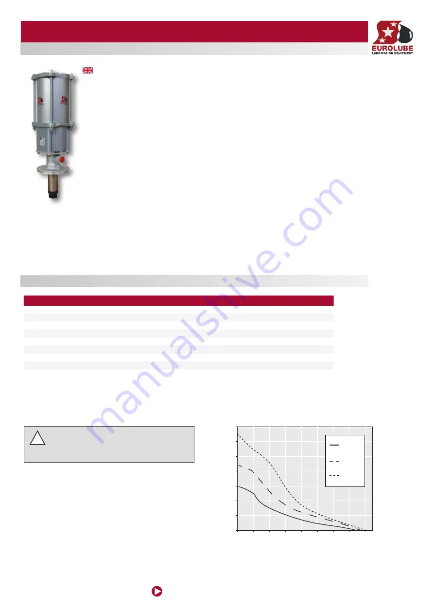
Pump Pressure/Flow
Test fl uid: 10W30 Oil
Fluid Pressure, bar
(psi)
Flow, l/min
(GPM)
5 bar
(70 psi)
7 bar
(100 psi)
10 bar
(150 psi)


