


©
EUROHEAT
DISTRIBUTORS (H.B.S) LTD. March 2012
E & OE Instructions Part number IN1156 Ed. E
27
H35 Burner Removal and Replacement
H35 Burner Bracket
The burner is held in place by two adjustable brackets, one either side of the
burner, secured by self-tapping screws.
Removal
Remove the logs from the top of the burner.
The two adjustable brackets holding in place the left and right sides of the burner need to be removed from
the stove. The retaining screws being located on the inner side panel of the stove.
Once these brackets have been removed the ceramic burner can be lifted out carefully.
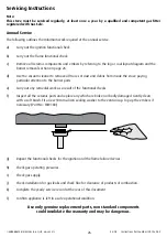
Always inspect the silicon sealing washer for signs of damage or wear and replace as a matter of course every
year.
Replacement
Lift the burner back into the stove.
The two adjustable side brackets should then be replaced, these brackets should be adjusted so that the burner
is level and when the centre is pushed down there is 1 to 2mm movement, see page 27.
H45 Burner Removal and Replacement
Removal
Remove the logs from the top of the burner.
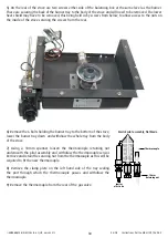
The burner is held in place by two adjustable
brackets, which secure the burner and
allow it to be levelled. They are located in
the left (A) and right (B) large holes in the
burner. Remove the wing nuts holding the
brackets in place and slide the brackets off
the threaded rods. The burner can then be
carefully lifted from the stove.
Replacement
Lift the burner back into the stove.
The two adjustable brackets should then be replaced, these brackets should be adjusted
so that the burner is level and when the centre is pushed down there is 1 to 2mm
movement, see page 27.
A
B
H45 Burner Bracket, Threaded Rod and Wing Nut