Input Section
8
5
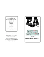
Source:
Two, 1 MEG Ohm, instrument inputs designed for maximum flexibility for all
musical instrument applications. DOUBLER ONLY: One low impedence Microphone
input with phantom power.
IIS or Intelligent Input Switching, which can be actuated from the front panel or with
an optional footswitch, is a microprocessor controlled CIRCUIT that senses which
channel is activated and allows for different combinations of channel control. With
your bass plugged into channel 1, the switch will let you access the EQ on channel 1
or channel 2 (i.e. clean/solo). With basses plugged into channels 1 and 2, the IIS will
toggle between Channel 1, Channel 2, or both Channels 1 and 2. Internal jumpers
settings will provide Effects/Tuner send on either Channel 1 or on both Channels 1
and 2.
Level Indicator Yellow LED
: The Level Indicator LED is a visual representation of
your input level. The LED should illuminate moderately under normal playing
conditions. Input gain can be adjusted with the Gain control knob and by the Input
Trim Pots (one for each channel) located on the top of the Micro and Doubler.
Gain Knobs
: The Gain knobs allows for maximum signal level and headroom. Gain for
each channel can be adjusted by the Gain knob and by the trim pot located on top of
the amp.
Input Trim Pots:
Located on the top, left of the Micro and
Doubler are two Input Trim Pots, one for each channel. See
“A Look Inside” for a diagram of the location of the Trim
Pots.
Using the Gain Knobs and Input Trim Pots:
The yellow LED
for each channel should illuminate moderately under normal
playing conditions with the gain knob about half way up. If
you are unable to get the Level Indicator LED to light with the gain knobs about half
way up, using a mini screwdriver, turn the corresponding Input Trim Pot clockwise to
increase the gain. If under normal playing conditions the Level Indicator LED lights
too easily with the Gain Knob at a low position, then, using a mini screwdriver, turn
the corresponding Input Trim Pot counter clockwise to decrease the gain.
Effects Section
The default setting for the Effects/Tuner Send and Return makes it available on
Channels 1 and 2 (see “A Look Inside”). Via jumper settings the Effects/Tuner Send
and Return can be available on Channel 1. There is no option for Channel 2 only.
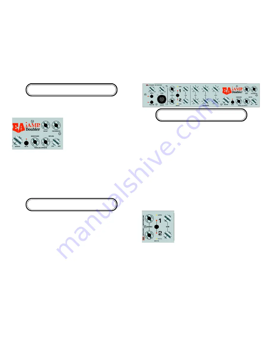
Parallel Effects/Tuner Send Jack:
Connect the
cord going to the effects box, pedal or tuner
here.
OUTPUT SECTION
Dry/Wet Control:
Use this control to adjust the
level of the signal returning from the effects
chain.
Footswitch:
An optional mono or dual momentary footswitch can be plugged into the
footswitch jack. When using a mono footswitch you will be able to control the IIS
channel switching function as you would with the front panel switch. When using a
dual momentary footswitch (with a stereo plug) you can additionally control the mute
function as you would with the front panel switch. The footswitch does not disable
the the front panel controls; rather they continue to work in parallel and picks up
where one leaves off. With a dual footswitch the “tip” controls the IIS while the
“ring” controls muting functions. The configuration of the Footswitch is handled by
internal jumpers. See “A Look Inside” for specific jumper settings. The factory default
setting is for a mono footswitch.
Rear Panel Functions
Power Switch:
Turns unit on/off.
A/C Input:
Use appropriately grounded, three-prong A/C plug.
Speaker Output:
One Speakon connectors, wired 1+, 1-.
Cooling Vents:
The vents on the top of your Micro or Doubler need to be kept clear.


