


Operating Instructions
Transponder-Coded Safety Switch CTP-I.-AS
8
(Translation of the original operating instructions) 2543028-02-01/21
6.2.
Guard locking on version CTP-I2
(guard locking actuated by power-ON and released by spring force)
Activating guard locking:
Apply auxiliary power to the solenoid and set AS-Interface output bit D0.
Releasing guard locking:
No auxiliary power at the solenoid and/or clear AS-Interface output bit D0.
The magnetically actuated guard locking operates in accordance with the open-circuit current principle. If the solenoid is
not controlled (D0=0) or if auxiliary power is switched off, guard locking is released and the guard can be opened directly!
If the solenoid is controlled via the AS-Interface bus (D0=1) and auxiliary power is applied to the solenoid, the guard locking
pin is held in extended position and the guard is locked.
6.3.
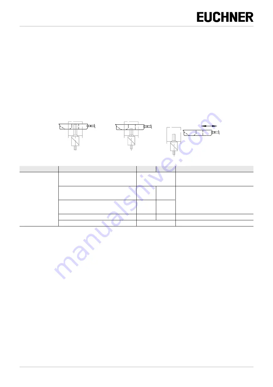
Switching states
Guard closed and locked
Guard closed and not locked
Guard open
Programming
State
D0, D1
D2, D3
Monitor diagnostics
Dual-channel
dependent
Synchronization time
≥ 100 ms /
Dual channel
positively driven
Guard closed
Code sequence
Green
If start-up test selected:
yellow flashing on start-up
Intermediate state during opening or closing of the
guard.
Switch S1 (internal) open
Half-se-
quence
00
On opening: yellow flashing
On closing: red
After expiration of the synchronization time:
yellow flashing
Intermediate state during opening or closing of the
guard.
Switch S2 (internal) open
00
Half-se-
quence
Guard open
00
00
Red
Address 0 or communication disrupted
–
Gray


