


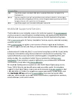

USRP-2900 Connectors and LEDs
Figure 3. USRP-2900 Front Panel
NI USRP-2900
70 MHz–6 GHz
ESD
SENSITIVE
TX OUTPUT MAX +20 dBm, RX INPUT MAX –15 dBm, ALL RF PORTS 50
Ω
RF 0
TX1 RX1
RX2
Designed by Ettus Research
Refer to the user documentation for required maintenance measures to ensure user safety
and/or preserve the specified EMC performance.
The signal pins of this product's input/output ports can be damaged if subjected to ESD. To
prevent damage, turn off power to the product before connecting cables and employ
industry-standard ESD prevention measures during installation, maintenance, and operation.
Table 1. Device Front Panel Icon Definitions
Connector Use
RX2
Input terminal for the RF signal. RX2 is an SMA (f) connector with an impedance of
50 Ω and is a single-ended input channel.
TX1 RX1
Input and output terminal for the RF signal. TX1 RX1 is an SMA (f) connector with an
impedance of 50 Ω and is a single-ended input or output channel.
Table 4. USRP-2900 Module Front Panel Connectors
LED
Description
Color Indication
RF 0 RX2
Indicates the receive status of the
device.
Off
The device is not active.
Green The device is receiving data.
TX1 RX1 Indicates the transmit status of the
device.
Off
The device is not active.
Green The device is receiving data.
Red
The device is transmitting data.
Orange The device is switching between
transmitting and receiving data.
Table 5. USRP-2900 Module LEDs
ni.com
14
USRP-2900/2901 Getting Started


