background image


21           |           24 


Etrel Load Guard | User manual 


 |   

In  the 

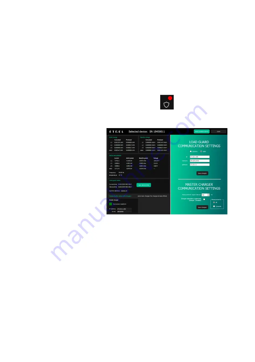
Load  Guard  Communication  Status

  window,  the  following 

information that Load Guard is transmitting, can be viewed: 


Total active power [kW]. 


Power [kW] and current [A] of phase L1. 


Power [kW] and current [A] of phase L2. 


Power [kW] and current [A] of phase L3. 

If the connection with the Load Guard is not successful, or the connection 
is interrupted, red dot will show at the Load Guard icon.  


The  Load  Guard  Configuration  software  windows  should  look  as  it  is 
presented on the following figure. 


Figure 37: Configuration windows 

During  charging  procedure  on  master  charging  station  or  any  other 
charging  station  of  this  cluster,  the  Load  Guard  would  measure  total 
consumption current of the charging station and other loads and send the 
data to the master charging station. 

If total current, that Load Guard measures, surpasses the set limitation of 
current (Max. building current), the master charging station will lower the 
target charging current of all charging stations in the cluster. This will be 
performed in a way that total current of all the charging station and other 
loads will not surpass the set limitation of current. 

Most of the electric vehicles can not charge with charging current of less 
than  6  A.  Because  of  this,  in  a  case  that  the  target  current  would  be 
lowered  to  less  than  6  A,  the  charging  would  be  temporarily  paused. 
Charging will continue when the Load Guard sends information that the 
total consumption is lower that the set limit for more than 6 A. 


Summary of Contents for load guard

Page 1: ...ETREL LOAD GUARD USER MANUAL Document version 2 1 Document date 30 7 2020...

Page 2: ...OMPUTER AND CHARGING STATION11 Computer IP Address 11 Charging Station IP Address 12 5 CONFIGURATION 14 Software for Configuration 14 Configuration of the Load Guard 16 Load Guard Network Settings 16...

Page 3: ...ue or increasing it to utilise the remaining available power for faster charging As Load Guard measures electric current in both directions it is capable of sensing the power surplus generated by loca...

Page 4: ...er supply but rather share available power with other consumers in the building Homes Apartment buildings Business fleets Parking spaces Commercial buildings PREREQUISITES FOR USE Load Guard connected...

Page 5: ...se or decrease the charging power or even stop it completely to prevent the fuses from switching off due to overcharging Load Guard allows charging with maximum current without overloading the fuses F...

Page 6: ...ONS DIMENSIONS 90 5 x 53 5 x 61 8 mm Width 3 TE on DIN rail WEIGHT 0 23 0 70 kg packaging adds 0 10 kg CLAMP CABLE LENGTH 70 cm CLAMP DIAMETER Small 16 mm large 24 mm CONNECTION Single phase or three...

Page 7: ...that is flowing back to the electrical grid In case of production of energy at the location it can turn up the charging power suppling the electric vehicle When bought at the same time the Load Guard...

Page 8: ...urrent transformers CONNECTING THE CURRENT TRANSFORMERS Figure 8 Connecting the current transformers THREE PHASE CONNECTION For proper three phase connection current clamps must be placed on specific...

Page 9: ...hases are not connected in correct sequence the Load Guard power calculation will be wrong Figure 10 Arrangement of input and output phases Measuring current transformers are connected to the Load Gua...

Page 10: ...pointing in the direction of energy flow SINGLE PHASE CONNECTION In case of single phase connection the measuring current transformer is set only on the phase conductor that is used as shown on the fo...

Page 11: ...nt photovoltaic cells batteries the measuring current transformers can be set on two conductors production conductor and consumption conductor In this case the Load Guard would be measuring the differ...

Page 12: ...rth must be different among the devices COMPUTER IP ADDRESS To obtain IP address of the computer the Windows Command Prompt is used Press Win R on the keyboard and in the presented window type cmd and...

Page 13: ...uard Configuration Software settings If this is not true the software could not find the Load Guard and even if Load Guard is found the configuration is not possible CHARGING STATION IP ADDRESS If the...

Page 14: ...Display of IP address after pressing the reset button for 5 s Figure 21 Selection of login mode The IP address of the charging station and the state of the connection with central system will be disp...

Page 15: ...solutions atlassian net wiki download attachments 258867203 Load Guard Configurator 1 4 zip api v2 Expand the compressed file in new folder Load Guard Configurator 1 4 Click on LoadGuardConfigurator e...

Page 16: ...uard information Load Guard serial number is important information In the above case it is 18430011 For establishing connection this serial number must be listed in charging station web interface Clic...

Page 17: ...re presented in a same way as on the above figure currents powers voltages times it means that the Load Guard Configurator software successfully connected to the Load Guard If the time on the Load Gua...

Page 18: ...t part of the same network group as the computer anymore e g switching of one of the first three numbers of the IP address only the IP address and serial number of the Load Guard will be displayed In...

Page 19: ...vailable the configuration of Load Guard can continue In IP address field the IP address of the charging station must be written also in the Serial field the serial number of the charging station must...

Page 20: ...he data that Load Guard is sending Confirm the setting with click on Save changes Figure 32 Setting the measurement report interval PAIRING OF CHARGING STATION WITH LOAD GUARD To connect to INCH charg...

Page 21: ...Serial number of the Load Guard must be written in the field Serial number in the presented case this number is 18430011 After that click on Save and restart the charging station If the communication...

Page 22: ...r the Load Guard would measure total consumption current of the charging station and other loads and send the data to the master charging station If total current that Load Guard measures surpasses th...

Page 23: ...is another connection enabled in the computer it must be disabled All of the possible connections should be disabled except the one used for the connection to the Load Guard NO CONNECTION BETWEEN LOA...

Page 24: ...ngle phase connection and in the Load Guard Configurator windows the voltage is not shown or it is very low 5 V it means that the supply of phase and neutral conductors of Load Guard are switched Note...

Page 25: ...isplayed total power is not correct because the power of the phase with negative power is subtracted Figure 41 The value of measured power is negative DISPLAYED POWER IS NOT CORRECT If the displayed p...

Reviews: