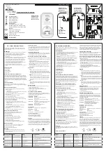
Installation manual (ver. 2/2018)
ETLOC-50 SECURITY
5
The vehicle unit has to be connected via the red wire to a
constant power supply without
current limit
. Protect this connection with a 5 A fuse.
Grounding
(black wire) must be done in the
shortest possible distance
from the car battery's
negative pole.
When the
engine is running there must always be
+12/24 volts on the
IGNITION input
(yellow wire).
The individual
wires
of the wiring harness
must be shortened
to the absolute necessary
length.
Cut the unused wires at the connector
and
insulate
their ends.
Description of the vehicle unit ETLOC-50 SECURITY connector
Pin 1
2 x black
a) vehicle GND b) backup accumulator GND
Pin 2
Yellow
IGNITION input (acti12/24 V)
Pin 3
White-green
Not connected
Pin 4
White-black
STOP output (activation GND)
Pin 5
Blue
Switching relay
–
contact close (NC)
Pin 6
Brown
Switching relay
–
common contact (COM)
Pin 7
Red
Main power 12/24 V
Pin 8
Purple
Not connected
Pin 9
White
Input ALARM 2 (activation GND)
Pin 10
Orange
Input ALARM 1 (acti12/24 V)
Pin 11
White-red
+ 6 V backup accumulator
Pin 12
Green
Switching relay
–
contact open (NO)
IMPORTANT
1
2
3
4
5
6
7
8
9
10 11 12
Overview of
the vehicle unit’s connector


