Etherstack SFFR-6 User Manual Download Page 14


SFFR-6 

User Manual 

Getting Started


Doc ID: ES1002-UM02-v204a


Copyright © 2014 Etherstack London Limited


Page 14 of 39 


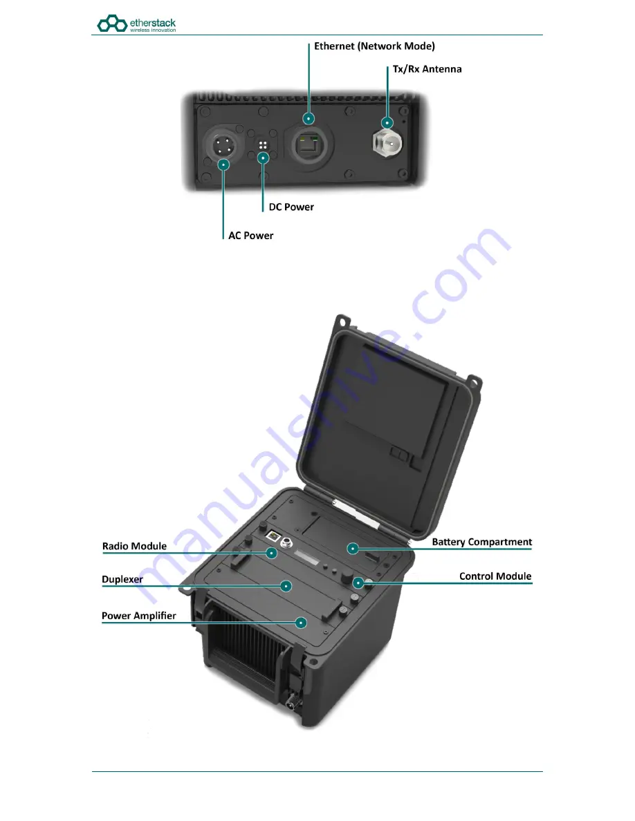
2.2.3  Interface Module 

The interface module will vary based on the options purchased when your GoBox was ordered. 

The interface module presents both AC and DC connectors, combined transmit and receive antenna connector or separate 
transmit and receive antenna connectors and/or an Ethernet port for use in Network mode. 


Summary of Contents for SFFR-6

Page 1: ...SFFR 6 User Manual SFFR 6 USER MANUAL Version 2 04a February 2015 Small Form Factor Tactical Repeater and Base Station...

Page 2: ...uration 18 3 1 Before you begin 19 3 1 1 About GoBox Configuration Files 19 3 1 2 About Operational Profiles 19 3 1 3 About Duplexer Group Tags 19 3 1 4 What you need to program and test your GoBox 20...

Page 3: ...tration 33 4 4 1 Backing up your GoBox Configuration 33 4 4 2 Restoring your GoBox Configuration from a Backup 34 4 4 3 Clearing the Gobox Configuration from memory 34 5 Troubleshooting 35 5 1 Cannot...

Page 4: ...e dispositif est conforme la norme CNR 210 d Industrie Canada applicable aux appareils radio exempts de licence Son fonctionnement est sujet aux deux conditions suivantes 1 le dispositif ne doit pas p...

Page 5: ...ecially the heatsink areas Exercise caution when handling or carrying the unit if it has been operating under these conditions Attention Surfaces chaudes Certains des surfaces de l quipement peut deve...

Page 6: ...SFFR 6 User Manual 1 Introduction...

Page 7: ...rk GoBox s can also be networked together when connected to Etherstack s RFSS Network Controller via its on board Ethernet interface The GoBox can connect to an IP backhaul using Cat5 Cat6 or can conn...

Page 8: ...ion Duplexer Modules Quick Change Duplexer Module Standard 1 Duplexer Module Standard 2 or more Duplexer Modules Option Power Options AC Power Standard DC Power Standard 2 x Lithium Ion Batteries Stan...

Page 9: ...ogramming Port Ethernet Receive Control Module Standard Network Port Ethernet Transmit Interface Module Standard Network Port Ethernet Receive Interface Module Standard LCD Backlight Standard Software...

Page 10: ...520 MHz2 Channel Spacing 12 5 kHz 12 5 kHz Channel Step Size 2 5 3 125 kHz 2 5 3 125 kHz Modulation C4FM FM C4FM FM Duplexer Internal notch type single antenna 4 5MHz Minimum Split Internal notch typ...

Page 11: ...SFFR 6 User Manual 2 Getting Started...

Page 12: ...plug for your country of operation requested at time of order on one end and will have an IP67 rated coupling socket for connection to the GoBox on the other DC Power Cable The DC power cable will be...

Page 13: ...to release the GoBox lid 2 2 2 Lid The GoBox lid has been designed to prevent dust and water from entering the GoBox when the locking clamps are fully engaged Both locking clamps must be fully engaged...

Page 14: ...2 3 Interface Module The interface module will vary based on the options purchased when your GoBox was ordered The interface module presents both AC and DC connectors combined transmit and receive an...

Page 15: ...rce without the need to turn the GoBox off The battery compartment has also been designed to recharge batteries when an external power source is applied Battery charge and charging state is explained...

Page 16: ...for the yellow Rx LED will illuminate for the duration of the signal The red Tx LED will illuminate to indicate that the signal has been repeated 2 2 5 8 Power LED On power up the GoBox will perform a...

Page 17: ...ion To remove the Duplexer ensure the GoBox is off and all power sources removed Turn the locking screws counter clockwise to remove and lift the Duplexer module out 2 2 8 Power Amplifier The GoBox wi...

Page 18: ...SFFR 6 User Manual 3 Configuration...

Page 19: ...rofiles whose duplexer group tag field has been set to the same tag group as what is programmed in the duplexer Additionally an operational profile can be assigned as the default operational profile f...

Page 20: ...al programming cable A laptop or PC with a web browser and standard Ethernet cable is all that will be required to configure the GoBox Once configured the laptop is no longer required for GoBox operat...

Page 21: ...tly or via a network Open your web browser and type the following http 172 16 10 1 The configuration page above will display showing a navigation pane on the left and a content pane on the right At th...

Page 22: ...ed you can select All and then edit the profile once Duplexor Group tags have been created Selecting All means this profile option will always be available to select on the GoBox control interface reg...

Page 23: ...0xf7e F7E a repeater set for this NAC will repeat P25 signalling on any decoded signal received 0xf7f F7F a repeater set for this NAC will allow all incoming decoded signals and the repeater transmit...

Page 24: ...a NAC code P25ConventionalGroup The GoBox will unsquelch on both a NAC code and a Talkgroup Id NAC The NAC is a feature similar to CTCSS or DCS for analogue radios Repeaters can be programmed to only...

Page 25: ...play order find the profile you want to move in the list and click Move Up or Move Down to move the operation profile to the required position The display order on the screen will be the display order...

Page 26: ...l memory To do this use the following steps Click on the Duplexor menu item on the navigation pane and press the Edit button on the content pane to show the Edit Duplexor form The following fields wil...

Page 27: ...Duplexor Group Tag button on the content pane to show the Add Duplexor Group Tag form The following fields will be required to be completed Field Description Duplexor Group Tag A unique name for this...

Page 28: ...a Copyright 2014 Etherstack London Limited Page 28 of 39 Create or edit each operational profile and link it to a specific Duplexor by setting the Duplexor Group Tag field Back in the Duplexor Group T...

Page 29: ...SFFR 6 User Manual 4 Using the GoBox...

Page 30: ...oft reset indicated by a flashing Power LED When the Power LED returns to a solid state the operational profile will have been loaded and the GoBox is ready for use 4 3 Checking GoBox Status The GoBox...

Page 31: ...the GoBox will display the current operational profile 4 3 2 Web configuration interface 4 3 2 1 Checking Battery Status To access this page click on the Battery menu item on the navigation pane The...

Page 32: ...ation pane The duplexor status page will show the duplexor serial number receive centre frequency transmit centre frequency date last calibrated and the duplexor group tag used to link a duplexor to a...

Page 33: ...has successfully connected to the RNC 4 4 Administration 4 4 1 Backing up your GoBox Configuration To back up your GoBox configuration to your local computer click the Backup menu item on the left han...

Page 34: ...re button in the content pane A file browser will then be displayed where you can select a previously backed up configuration file 4 4 3 Clearing the Gobox Configuration from memory To clear all GoBox...

Page 35: ...SFFR 6 User Manual 5 Troubleshooting...

Page 36: ...if the problem persists turn the GoBox off and remove and reinsert the control module If the error still is present when power is reapplied contact support 5 3 Status Window display Err xr1 or Err xr...

Page 37: ...SFFR 6 User Manual 6 Glossary...

Page 38: ...CO Association of Public Safety Communications Officials AVL Automatic Vehicle Location MMI Man Machine Interface NAC Network Access Code OTAR Over the Air Rekeying PTT Push To Talk P25 Project 25 RFS...

Page 39: ...e All rights reserved No part of this publication may be reproduced transmitted transcribed stored in a retrieval system or translated into any language in any form or by any means electronic mechanic...

Reviews: