


TMCM-1310 TMCL Firmware V1.11 Manual (Rev. 1.16 / 2014-MAR-19)
88
www.trinamic.com
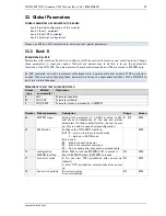
9.8
Current Regulation
This section explains the
current
amplitude regulation of the closed loop system. Basically, the self-acting
current regulation is used to improve drive efficiency by adapting the current level to a value that is just
sufficient enough to move the load with the desired speed. To achieve this, the current amplitude is
automatically adapted based on the actual position error and the configured parameters. This way, energy
cost can be kept down and heat dissipation can be reduced.
In case this is not desired, the feature can be switched off completely using axis parameter 122 (
current
scale enable
). Then, the motor is simply driven with the configured maximum current level. Nevertheless, it
is still in closed loop mode and does not lose any steps or stall.
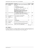
Current Scale
Factor (GAP 123)
position error
(GAP 14)
45°
90°
135°
0°
I_SCALE_MIN
(SAP 113)
-45°
-90°
-135°
I_SCALE_MAX
(SAP 114)
X_TARGET
(SAP 0)
Current Scaler Lower
Error Limit (SAP 116)
Current Scaler Upper
Error Limit (SAP 117)
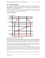
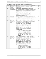
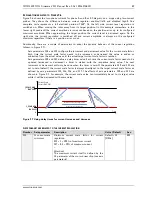
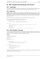
Figure 9.5 Basic principle of position error dependent current amplitude regulation
E
XPLANATIONS RELATED TO
F
IGURE
9.5
Based on the position error with respect to the actual target position, the current amplitude (which is the
length of the current vector of phase A and phase B current) is adapted. The red lines in Figure 9.5 show
the position error dependent
target current scale factor
.
The target current amplitude is defined by four axis parameters as shown in Figure 9.5:
-
Axis parameters 113 and 114 define the minimum and maximum current scale value, which are factors
the maximum current (as defined by axis parameter 6) is scaled with.
-
With axis parameters 116 and 117 two error limits can be configured. Within these two limits the
current is scaled (increased or decreased) using a linear function.
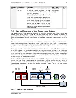
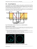
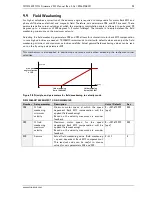
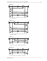
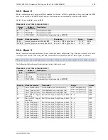
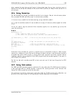
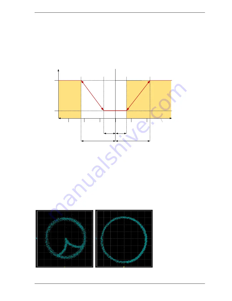
Figure 9.6 Basic principle of position error dependent current amplitude regulation