background image

52

SmartFade ML v3.0.1 User Manual

N o t e :

The shape effects are tailor designed with some common lighting situations in mind. Feel 

free to experiment in any other way. Remember that a moving head with tilt at 50% will 

never do a circle or square, it will appear as a figure-8 - it needs to be pointing forward or 

backward. Here is some information about them.

1. Circle

 - A circular fading movement 

2. Square

 - A square fading movement

3. Infinity

 - A never ending journey in smooth moves

4. Lissajou 

- A pendular movement

5. Clover

 - The path outlining a four leaf clover

6. Flower

 - The path outlining a flower 

7. Triangle

- A triangular fading movement

8. Harmonics

 - A fast flower movement

9. Noise

 - An irregular and erratic movement pattern

10. Pentacle

 - The path outlining a pentacle

11. Skating

 - The movements of a skater seen from top

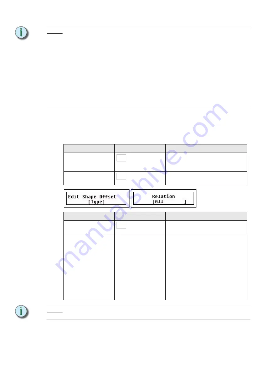
Offset Relations In Shape and Color Effects

’s possible to offset each device that is affected by a Shape or Color effect, so that they do 

not appear to move the same way all the time, instead breaking into smaller groups. This 

information is stored individually in each Memory or Stack state. 


N o t e :

To make sure you can use the same effect with different relations, the relation is stored 

in the memory or Stack state only - it is not part of the effect itself. 

Action

Console

Feedback

1. Select Fan mode

This button lights up. EFFECT will blink. If any 

devices are selected the parameter bump 

buttons will blink as well.

2. Select effect 

FAN and EFFECT will blink. The Offset Rela-

tion menu is opened in the LCDs. 

Menu choice

Console

Feedback

Type

Toggles between Shape and Color effects for 

the selected Devices.

Relation

Wheel 3

Select relation

ALL

Evenly

1:2

1:3

1:4

1:5

1:6

1:7

1:8

1:9

FAN

EFFECT

SEL

Summary of Contents for SmartFade ML

Page 1: ...Console User Manual Version 3 0 1 Copyright 2011 Electronic Theatre Controls Inc All Rights reserved Product information and specifications subject to change Part Number 7219M1210 3 0 1 Rev A Released...

Page 2: ...Imagine Focus Express Unison Obsession II SmartPack SmartFade ETCNet2 EDMX Source Four Revolution Sensor and WYSILink are either registered trademarks or trademarks of Electronic Theatre Controls Inc...

Page 3: ...onalities from Card 7 Load Personalities from Card 7 Format SD Memory Card 8 Chapter 1 General Information 9 Control Capacity 10 Frontpanel Functionality 11 General Buttons 11 Faders Bump Buttons 12 M...

Page 4: ...ion 28 LED Calibration 28 Save LED Calibration 28 Load LED Calibration 28 MIDI Setup 29 MIDI Show Control 29 Synchronising Two SmartFades 30 Basic MIDI Implementation 30 MIDI Channel 31 Sending MIDI C...

Page 5: ...Stack State or Cue 62 Chapter 4 Edit 65 Edit Memories 66 Edit a Memory 66 Delete a Memory 67 Delete Multiple Memories 67 Copy a Memory 67 Default Device Times 68 Memory FCB Times 68 Edit Sequences St...

Page 6: ...ut from Memory Faders 84 Examples of Using Memory Faders 84 Sequences 85 Select Fader Page 85 Sequence Bump Modes 85 Rate BPM for Sequences 86 Stack Crossfader 87 General Crossfader Controls 87 Stack...

Page 7: ...ual control memory driven operation and an impressive array of features for systems work SmartFade ML is perfect for any venue usable for small touring shows auditorium productions or as a stage manag...

Page 8: ...or MORE buttons Displays are shown like this Text Conventions Buttons in tables are shown as images Buttons in text are indicated with bold capital letters followed by the word button Like STACK butto...

Page 9: ...on back panel Dimmer manufacturer and installation type Other components in your system Unison other consoles etc Americas Electronic Theatre Controls Inc Technical Services Department 3031 Pleasant...

Page 10: ...hutdown procedure the SmartFade ML console will complete any pending operations and save any system data as required to ensure error free startup at the next session Disconnecting power from the conso...

Page 11: ...le must be off The LCD shows the Operating Modes menu 2 Select mode Wheel 3 Full control All functions available Control Playback No recording or patch functions Playback only All intensity and device...

Page 12: ...the file menu CAUTION Only standard SD Memory cards or connection to a PC via USB may be used for updating the software on a SmartFade console Software update is not possible using an SDHC Memory car...

Page 13: ...otherwise it will jump to the Save as menu Load show from Card This is done from the Save Load Show menu Menu Save Load Show Load show Select the show with the wheel The default show offered for loadi...

Page 14: ...ality from will be the lowest numbered recording on the card The reason for this is that you may want to save a dummy show Load Personalities from Card The console has a personality library with 500 o...

Page 15: ...to your PC CAUTION Formatting your SD Card will erase any information stored on the card Be sure to remove any important files from the card before formatting CAUTION Only standard SD Memory cards or...

Page 16: ...Right click on the SD card icon and select Format This will open the formatting window Step 4 In the File System field select FAT This will establish the card s file system as FAT16 Step 5 Click Start...

Page 17: ...General Information This chapter gives you the general information you need to get started This chapter contains the following sections Control Capacity 10 Frontpanel Functionality 11 Philosophy of t...

Page 18: ...ects section Devices need to be patched before they can be used See Patch Devices on page 23 The intensity channels for the devices are automatically mapped to and can be controlled from the faders ju...

Page 19: ...so be held with other buttons for some special functions this is described in this manual where it so applies Undo The UNDO button is used to reverse some specific situations This applies only to the...

Page 20: ...page 82 Bump buttons with memories can be set to activate device parameters without bumping intensities by activating the GO MODE button See Memory Bump Modes on page 83 Note For intensity faders to c...

Page 21: ...Edit on page 65 The Select Section This section of 24 buttons is used to select devices groups palettes and effects It uses the buttons in the Attributes Selection and Modify sections to do this See D...

Page 22: ...o see programmed intensities for MEMS faders 1 24 Action Console Feedback Activate menus Scroll through choices Wheel 3 Choices are shown over the wheel Use the Menu button again to move to subsequent...

Page 23: ...rom the Crossfader either up or down Set levels will fade out when the Crossfader is operated Device Parameters All device parameters operate exclusively live using Latest Takes Precedence LTP This me...

Page 24: ...ties or any single device parameter and 11 Color effects for color mixing devices The effects are referenced as sources just like palettes Offset is stored in the memory but not Depth and Speed Those...

Page 25: ...e patched since they require a specific personality corresponding to each type There are other user Settings for displays and language These are described in this chapter This chapter contains the fol...

Page 26: ...intensity channels 24 device channels and 2 independent channels The D1 24 channels can be patched directly to dimmers in the patch by channel dimmer menus as well Each console channel can be patched...

Page 27: ...INT A and INT B is set 1 1 from the Patch Menu Menu Patch Patch Set Clear Set INT Patch 1 1 Press OK to confirm Note The Device Intensity channels can be used to patch 24 more conventional lights if n...

Page 28: ...values until changes in the patch override any active channels Note A dimmer can only be patched to one control channel at a time If you patch a dimmer and then later patch the same dimmer to a differ...

Page 29: ...re more than three dimmer outputs patched to the same intensity channel Note You can patch any of the D1 24 intensity channels to conventional dimmers This is useful if you need more than 48 intensity...

Page 30: ...nts IND 1 DMX 511 IND 2 DMX 512 This is easy to remember and provides immediate control with two outputs It is also possible to create a custom patch by assigning any DMX outputs to the independents T...

Page 31: ...about 500 standard device personalities A separate file that you can download from www etcconnect com called PERSLIB BIN may be placed on an SD card and browsed on the console or in the simulator in S...

Page 32: ...olor scroller or other conventional fixture accessory the light source is controlled by a conventional dimmer This has to be patched in the channel or dimmer patch separately to a device intensity cha...

Page 33: ...t rigged in the same way to make pan and tilt have the same result on stage These functions are available from the Device Menu Go to Menu Devices Menu choice Console Feedback Invert Pan Wheel 2 select...

Page 34: ...fault Fade Times on page 74 Move Dark Time Palette Time Crossfade Faders The direction in which the Crossfade faders advance to the next step in STACK mode is set in the Setup menu Menu Setup Crossfad...

Page 35: ...e DMX Out Speed on page 18 MIDI Settings See MIDI Settings on page 27 Language You can choose language for the menus from the Setup menu Menu Setup Language English Current choices are English Fran ai...

Page 36: ...on mode they are all set to white Press a specific select button to change its calibration The button number will be indicated on the right display Devi If you press the same device button again you w...

Page 37: ...e set to send any MIDI controller 1 127 to control external devices For show control and synchronising playback it is normally enough to make a MIDI connection and start using without having to set up...

Page 38: ...sed These functions are transmitted from within the Basic MIDI implementation on the currently set MIDI channel MIDI Channel page 31 Basic MIDI Implementation page 30 Basic MIDI Implementation A set o...

Page 39: ...trol channel in SmartFade ML to control an external device using any MIDI controller 1 127 This is set up in the Controller Patch Menu Setup MIDI Controller Patch Use the wheel 1 to select SmartFade M...

Page 40: ...fter being patched they must be repatched for the changes to be updated Open the Personality Editor Step 1 Select the menu Patch Personalities Menu Patch Patch Devices User Personalities Use MORE to s...

Page 41: ...owing way of working is very fast and direct Step 2 Select INT A move fader 1 and set the first control channel of the device to an appropriate HOME value check the documentation of the device to find...

Page 42: ...omfortable for some operators especially if there is no device connected Step 1 Open the personality editor as described prior to this Step 2 Select a channel offset with encoder 1 Step 3 Press a bump...

Page 43: ...Blue Typically moving lights with filters are CMY mixers and LED luminaires with discrete LEDs are RGB mixers There are some exceptions so it is recommended to study the manufacturer s data to decide...

Page 44: ...Fine The PAN and TILT bumps will toggle the assigned parameter between Coarse and Fine Step 1 Select the first offset channel with encoder 1 Step 2 Use the PAN parameter bump button 2 to toggle to pan...

Page 45: ...de for each parameter fader in Param 1 and Param 2 The bump button will light up when the FWI mode is active Special Invert Parameter When you have assigned your parameters in live or blind press MENU...

Page 46: ...38 SmartFade ML v3 0 1 User Manual...

Page 47: ...e you have set up your console to control the dimmers and devices in your rig you can start programming This chapter contains the following sections Intensity Channels 40 Devices 42 Effects 51 Memorie...

Page 48: ...l be situations where the physical position of the fader does not match the output of the fader When you move an unmatched fader the bump button will blink until the actual level is matched by that of...

Page 49: ...Menu choice Console Feedback START Wheel 1 Select first channel in range END Wheel 2 Select last channel in range All Selects all channels as channel range Adjust LEVEL Wheel 3 Adjust the levels propo...

Page 50: ...amming and playback will be easier if you prepare Palettes and Groups for quickly selecting and adjusting devices See Palettes on page 16 See Groups on page 16 Device Times There are two default time...

Page 51: ...ice The buttons toggle selection of each device Hold one and press another to select a range Press twice fast to deselect all other devices Clear current selection Clears all selected devices Get prev...

Page 52: ...EAR to exit 3 Select groups GROUP lights up All 24 select buttons will blink at full Already recorded ones will blink dimmed 4 Record group As soon as a select button is pressed the group is stored to...

Page 53: ...the fader which may be unwanted behavior To adjust parameters relative to their current value use the encoder wheels and LCDs Bump buttons The bump buttons will toggle a parameter between zero and fu...

Page 54: ...l of Hue Saturation Color wheel 1 and 2 plus MODIFY and Color FX The LCD s provide parameter control with the encoder wheels which is necessary when you want to adjust parameters relative to their cur...

Page 55: ...s as long as those devices were included when the palette was recorded Note For devices with a color mixing system color palettes 1 24 are auto generated The select buttons will reflect the color of t...

Page 56: ...ight up at full 3 Select palette As soon as a select button is pressed the pal ette is activated The console will automati cally return to Device Select mode Action Console Feedback Home all parameter...

Page 57: ...sed Fan Menu Mode Note Center The order in which the devices are initially selected is used to calculate the center device Select 1 2 3 and center device 2 Select 3 1 2 and center device 1 In an even...

Page 58: ...s to be active 2 Activate Highlight mode This button lights up 3 Select a device within the first selection This button lights up and the device is set to full The other devices are set to zero Adjust...

Page 59: ...p Shape Effects Shape effects can be stopped individually for any device Action Console Feedback 1 Select devices Selected device buttons are lit to full Device Select mode has to be active 2 Activate...

Page 60: ...tacle 11 Skating The movements of a skater seen from top Offset Relations In Shape and Color Effects s possible to offset each device that is affected by a Shape or Color effect so that they do not ap...

Page 61: ...enta yellow 11 Primary Steps through the primary colors red green blue Note Effects are only referenced to Memories and Stack steps When effects are modified they will be updated also where they have...

Page 62: ...Fade up snap off like a ramp s Action Console Feedback 1 Select devices Selected device buttons are lit to full Device Select mode has to be active If you are applying the effect to intensity channel...

Page 63: ...lete output exactly as it is Record Selected Records selected devices Parameter types can be masked All intensity channels with a level above zero will be recorded Record All Test Memory Press CLEAR f...

Page 64: ...is pressed will be unlit and its parameters masked from recording You can filter out single parameters from recording by holding FOCUS COLOR or BEAM and toggling off the parameter but tons The paramet...

Page 65: ...will light at full in red Record a Snapshot Copy a Snapshot to a Memory It s possible to copy a Snapshot to a memory in the Memories menu Menu Memories Copy Snapshots Use SEL to choose between Live an...

Page 66: ...sequences in MEMS mode have yellow bump buttons Each step of a sequence can contain one of two items One single dimmer or device intensity channel from INT A INT B or DEVICE INT A memory from any of t...

Page 67: ...memory or sequence stored already this button will be dimmed press CLEAR to exit 2 Choose location change page if desired The moment the bump button is pressed the button will turn yellow Now all bump...

Page 68: ...the wheels during playback They can also be set in the Sequence Time menu afterwards See Sequence Stack Times on page 74 Move While Dark Every stack step can have a Move While Dark flag This is a tag...

Page 69: ...and blink at full in each fader mode 3 If desired set the times for this step Wheels 1 2 4 If desired set Move Dark mode If off unlit all devices will move when GO is pressed for this step If on lit a...

Page 70: ...this mode will blink at full press CLEAR to exit 2 Choose Stack The Stack is selected and the buttons stop blinking 3 Select Record step or Update live step Wheel 3 Record all to the next free step Re...

Page 71: ...masked from recording Mask any intensity group if desirable Any button that is pressed will be unlit and it s intensity faders masked from recording 3 Select Record Step selected step or Update Live...

Page 72: ...64 SmartFade ML v3 0 1 User Manual...

Page 73: ...d recording information as described in Program you can play back this information and you can edit it This chapter is about editing This chapter contains the following sections Edit Memories 66 Edit...

Page 74: ...ities or device parameters Programming functions Make any changes with all normal program ming functions for intensities and devices See Program on page 39 Intensities are edited with intensity faders...

Page 75: ...target memories Each time you press a bump button that memory is deleted Let go of DELETE to exit You can only press UNDO for the last deleted memory Action Console Feedback 1 Activate Copy mode This...

Page 76: ...ecuted with the Bump button in GO mode See Memory Bump Modes on page 83 Step 1 Press EDIT Step 2 Press TIME Step 3 Now press a bump button for a memory The display will change to time setting Step 4 P...

Page 77: ...to use change instead to change to a different single intensity channel Unique Stack steps are edited as described just like memories Step 1 Press EDIT Step 2 Select Sequence by pressing a bump button...

Page 78: ...the data previous to this action Insert a Step Step 1 Press EDIT Step 2 Select Sequence by pressing a bump button or press STACK Step 3 Select Step wheel 1 and Insert wheel 3 The new step will be inse...

Page 79: ...continue with Actions from Step 2 Change the Content of a Step Use this function to change the memory or channel content of a step to another content Step 1 Press EDIT Step 2 Select Sequence by pressi...

Page 80: ...tion will blink Empty ones blink at full occupied ones are dimmed 3 Select target As soon as the button is pressed the source sequence is recorded The console will auto matically return to it s previo...

Page 81: ...confirm Step 6 Done Press EDIT to exit Menu choice Console Feedback Loop Wheel 3 Default behavior for Sequences not avail able for the Stack The Sequence will loop from the last step back to the first...

Page 82: ...of the Stack during playback This can be done for the last fade normal or the next fade NEXT active Press TIME with STACK active The set times are stored Rate The RATE button can provide Rate and Fad...

Page 83: ...p button for a sequence You will get this display Step 4 Use encoder wheel 3 to select Single step Press MENU to confirm Step 5 Use encoder wheel 3 to select a step Press MENU to confirm Step 6 Use th...

Page 84: ...ep 2 Press TIME Step 3 Now press a bump button for a sequence You will get this display Step 4 Use encoder wheel 3 to select All steps Press MENU to confirm Step 5 Use the wheels to set Global Timing...

Page 85: ...t Effect mode This button lights up The Effect select but tons light up full empty ones are dimmed 2 Select Effect to edit The selected effect select button will blink The effect menu is opened in the...

Page 86: ...e selected effect select button will blink The select parameter menu is opened in the right LCD Select what parameter type the effect will be applied to by pressing a bump button in PARAM 1 or PARAM 2...

Page 87: ...or effects 1 11 Buttons with created effects are bright empty ones are dimmed 2 Select Effect to edit The displays will switch to effect editing for this effect If it already existed it will be starte...

Page 88: ...parately and parameter by parameter Edit a Palette Action Console Feedback 1 Select devices Selected device buttons are lit to full Device Select mode has to be active 2 Make changes Parameter functio...

Page 89: ...ck As soon as you have programmed information you can play it back in different ways This chapter is about playback functions This chapter contains the following sections General Functions 82 Memories...

Page 90: ...n that will bring you back to a clean state of the console with no output Pressing CLEAR will NEVER erase content it only brings the fader intensities to zero You can press CLEAR to abort any recordin...

Page 91: ...y Bump Modes When a bump button is pressed there are different behaviors for memories depending on two modes SOLO and GO MODE Pile on or Solo The content of memory faders can be bumped to the level of...

Page 92: ...e parameters have been stolen by fader 2 and are only stolen back when a fader is brought up from zero Step 6 Bring fader 1 back up The devices will fade into the intensities and parameters of this fa...

Page 93: ...an be bumped to the level of the BUMPS fader in two ways This is controlled with the SOLO button OFF The level generated by pressing a bump button adds into the live output ON The level generated by p...

Page 94: ...next step starts Original wait timing is not lost and may be recovered by clearing the BPM time Clearing Rate Fade BPM Menu choice Console Feedback Rate Wheel 1 Set a Rate that will scale the total ti...

Page 95: ...ed lit at full and connected to the Crossfader controls The cue stack is loaded onto the Crossfader at step 0 a non existent step before step one so that pressing GO or starting a manual fade will fad...

Page 96: ...of the whole Stack temporarily When a Rate or Fade override is cleared the original times are retained Press RATE and then STACK Reset Rate Action Console Feedback Activate GOTO mode held As long as...

Page 97: ...ade with Times You can activate the TIME button and set default fade times with the wheels Press GO to execute a crossfade using these times Action Console Feedback 1 Activate Next mode The intensity...

Page 98: ...ible using an SDHC Memory card Update the Software SD Card Update If you are using an SD card for the very first time make sure it is formatted correctly FAT16 or it will not function with SmartFade M...

Page 99: ...3 Double click on the SFDownloader exe application you downloaded from the ETC Web site You should get this display Step 4 Start the console in test mode This is done by holding down the MENU button...

Page 100: ...efinition of 18 E Edit a memory 66 Edit step times blind 75 Edit the content of a Step 69 ETC locations 3 F Fade With Intensity 37 Fan 49 Fetch Parameters 50 G Global Time 76 Go Mode 83 H Highlight 50...

Page 101: ...cted 56 63 RGB 34 S Save Show to card 6 SD Card Update 90 Select Fader Page 85 Set Times Live 74 Shape effects 51 Shutdown 4 shutdown 4 software updating SD Card 8 software update 90 T technical servi...

Page 102: ...94 SmartFadeML v2 1 User Manual...

Page 103: ......

Page 104: ...8752 8486 Holzkirchen DE Ohmstrasse 3 83607 Holzkirchen Germany Tel 49 80 24 47 00 0 Fax 49 80 24 47 00 3 00 Hong Kong Rm 1801 18 F Tower 1 Phase 1 Enterprise Square 9 Sheung Yuet Road Kowloon Bay Ko...

Reviews: