ETC Installation Guide
SmartSwitch to Echo Relay Panel Feedthrough Retrofit Kit
SmartSwitch to Echo Relay Panel Feedthrough Retrofit Kit
Page 5 of 14
ETC
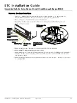
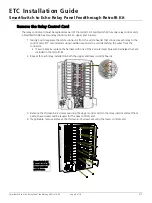
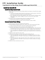
Remove the User Interface
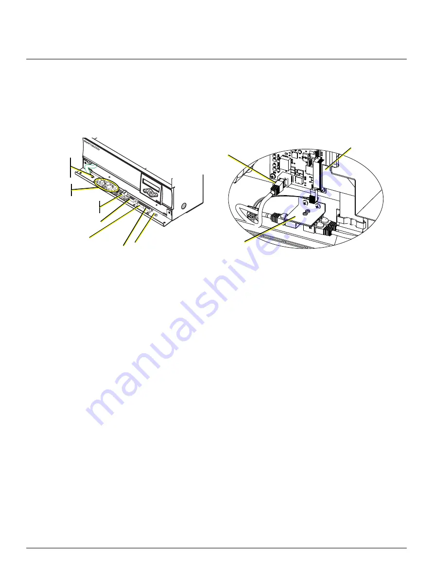
1. Using the Phillips screwdriver, remove the two M5 screws securing the I/O panel below the
Smartswitch User Interface. The panel should now open by folding downward.
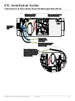
2. Remove the ground wire from the spade on the I/O card.
3. Disconnect all other cable connections that are preventing the panel from being removed.
4. Label all remaining wires.
5. Remove the I/O panel. This panel is no longer needed and can be discarded.
6. Remove any remaining adhesive-back cable mounts.
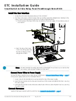
7. Remove the four 8-32 x 3/8 inch screws that secure the User Interface to the rear of the SmartSwitch
enclosure. Set the screws aside; they will be reused to secure the new User Interface to the same
location in the panel.
8. Remove the User Interface from the SmartSwitch panel. The User Interface is no longer needed and
can be discarded.
v
v
v
Ribbon cable
RJ45 to upper relay
control card
RJ45 splitter board
(in 48 circuit panel
only)
I/O panel
ground to
chassis
LinkPower
supply
Data communication
to CPU
Emergency/SmartLink
DMX In
DMX Pass-Thru
ESD drain wire
ground


