ETC Installation Guide
SmartSwitch to Echo Relay Panel Feedthrough Retrofit Kit
SmartSwitch to Echo Relay Panel Feedthrough Retrofit Kit
Page 10 of 14
ETC
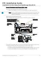
Connect Termination Board Harness (Com. Buss)
The termination board harness is factory installed at the com board.
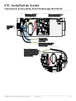
1. Press the white and black two pin connector into the header on the upper relay control card.
When working with a 48-position panel:
There is an additional wire connection from the upper control card to the lower control card.
A second pair of red and black wires is included as part of the termination board harness. This pair of wires
runs from the upper relay control card to the lower relay control card as shown above.
1. Feed the second pair of wires through the access hole near the power supply.
2. Guide the wires behind the circuit board, and through the grommet to the lower relay control card.
3. Press the white and black two pin connector into the header on the lower relay control card.
Note:
There is an additional length of red and black wire that is only used for a 48 -position panel
retrofit. With a 24-position retrofit, tie these extra wires back and out of the way. See
graphic on following page.
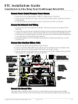
Header on
lower relay
control card
**UI mounting
panel removed for
clarity
Existing power
wires
Header on upper
relay control card
Factory installed
connection.
Wires routed
through
grommet
Second pair of wires for the ERP48-FT.
*These wires are not needed for a
24-position panel retrofit and will need to
be dressed neatly out of the way.


