ES5338.1 Carrier Board for Wheel Speed Sensor Simulation - User’s Guide
36
Connections and Plug Connections
ETAS
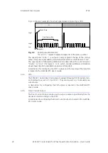
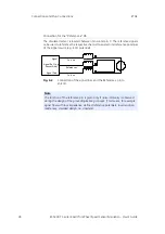
Connection for the "Reference x" Pin .
The simulated sensor is located between pin A and pin C. The reference signals
ca be used to reference the respective channel to an electrical reference potential
of the signal source (e.g. ECU potential).
Fig. 4-2
Connection of the signal lines and the Reference x pin to
an ECU.
Note
The function of the reference pin is given only if noise immunity is observed
during the design of the grounding/cabling concept. (This means, for example,
signal flow with low impedance, defined reference potentials, low transition
resistances, shielded design, no crosstalk).
Curr x p
Reference x
Curr x n
Signal
Signal Ref. (e.g.
Sensor Gnd)
Signal Gnd

