ES5338.1 Carrier Board for Wheel Speed Sensor Simulation - User’s Guide
24
Design, Installation and Fuses
ETAS
Assembly of the PB5338CURR.1-A Piggyback on the ES5338.1 Carrier
Board
The assembly of a PB5338CURR.1-A Piggyback on the ES5338.1 Carrier Board is
described below.
Proceed analogously with the assembly of additional PB5338CURR.1-A Piggy-
backs
1. Ensure that ESD-compliant conditions exist at your
workplace.
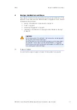
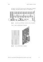
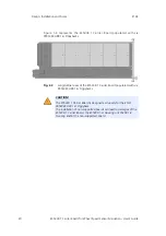
2. Align the PB5338CURR.1-A Piggyback to the
respective guide bolt (red dashed rectangles in
Fig. 2-7) of each slot of the ES5338.1 Carrier Board.
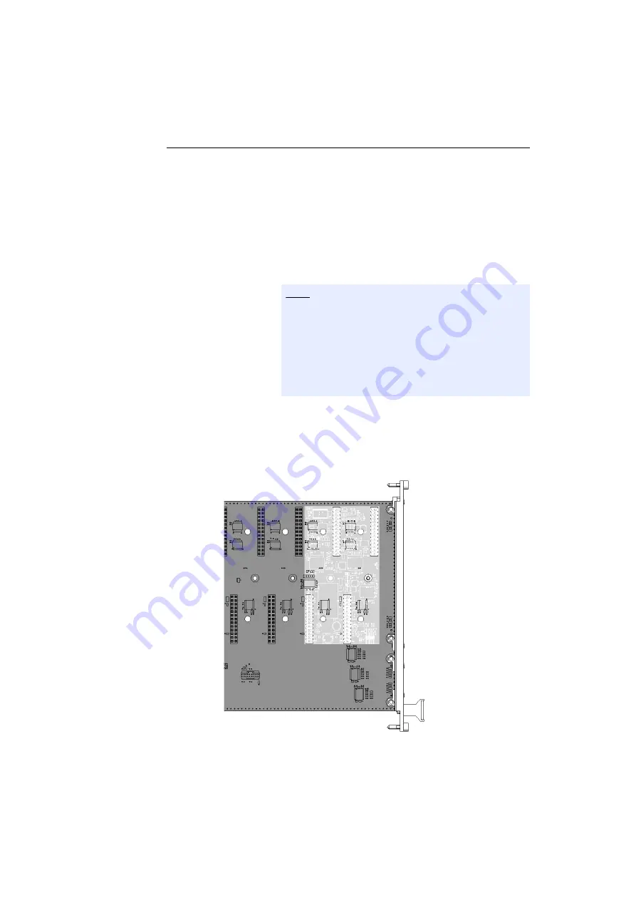
3. For each Piggyback, 4 connectors must be con-
nected (marked in Fig. 2-6).
4. When the alignment to the guide bolts and connec-
tors is correct, secure the PB5338CURR.1-A Piggy-
back with slight pressure.
Fig. 2-6
Installed PB5338CURR.1-A Piggyback
Note
The alignment must also be done to the connectors!
For each Piggyback, 4 connectors must be connected
(see Fig. 2-6).
Note that the guide bolt does not contact any elec-
tronic components or create any mechanical stress
during the installation of the PB5338CURR.1-A Pig-
gyback (indicated by the red arrow in Fig. 2-7).

