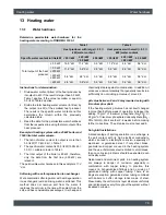
background image

ETAtouch controller

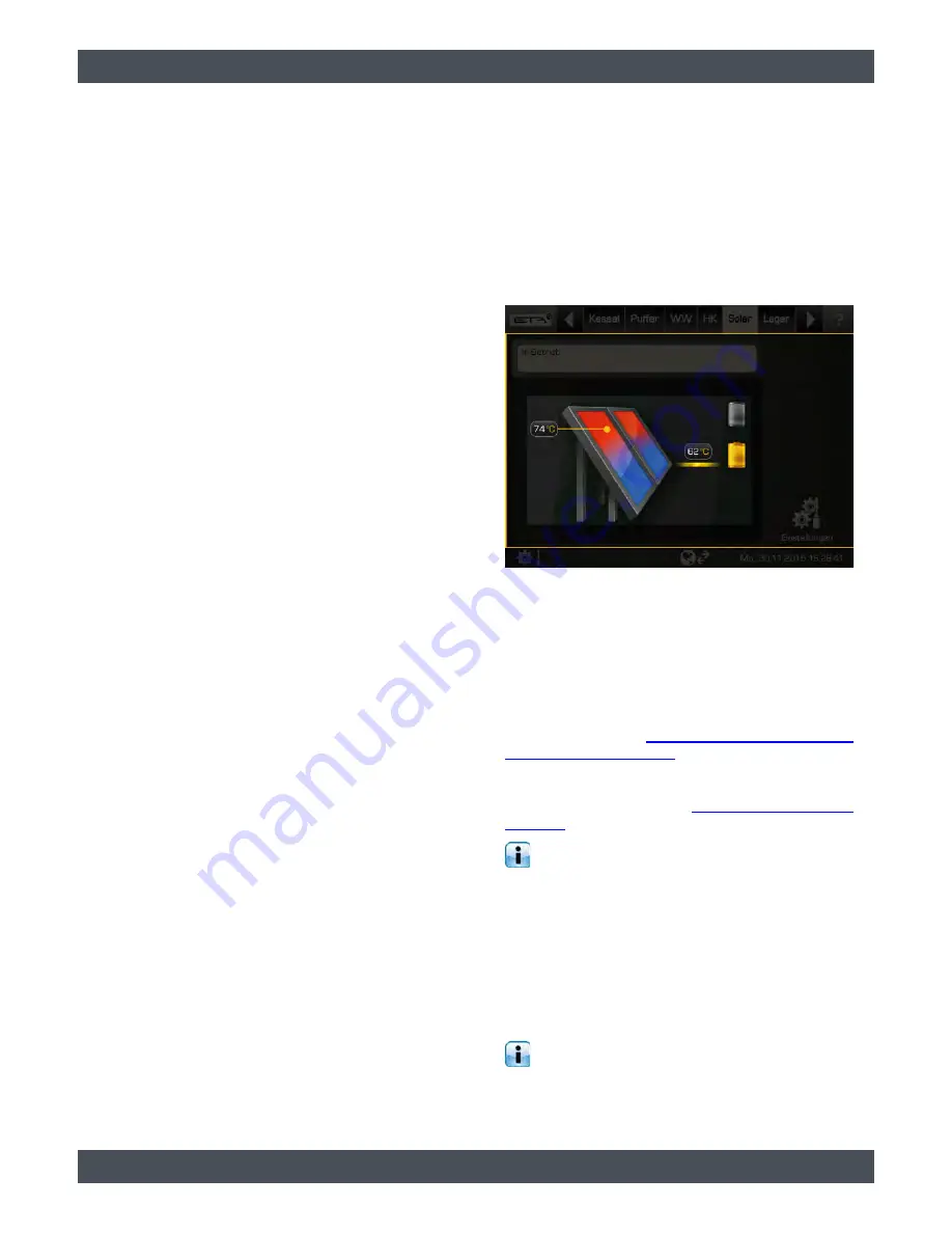
[Solar] function block

69

In solar heating systems with external heat
exchangers, experience has shown that most of the
energy from the solar heating system goes to the tank
in this control principle.

9.8.5

Solar heating system with external 
heat exchanger and stratified 
charging valve

Solar heating system with external heat exchanger
and stratified charging valve

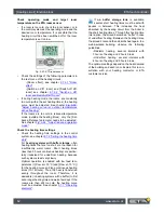
This variation of solar heating system also aims to
produce a sufficiently high temperature in the upper
area of the buffer, so the boiler does not have to start
for hot water charging.

Fig. 9-62: Solar heating system with external heat exchanger 

and stratified charging valve

The collector pump starts as soon as the collector is
warmer than the target temperature in the upper buffer
area [Buffer target solar].

The control principle is identical to that of a buffer with
two internal coils. The conditions for solar charging into
the upper buffer coil are also the same. They are
described in chapter 

9.8.3 "Solar heating system for

buffer with 2 internal coils"

.

The speed control of the secondary pump is identical
to that of a solar heating system with an external heat
exchanger, see chapter 

Fig. 9-61: "Regulation

principle"

.

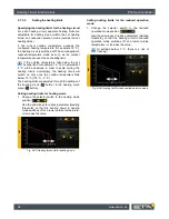
The only difference is the switching of solar
charging from the lower buffer coil to the upper. If

the conditions for solar charging into the upper coil are
not met, the lower coil will be charged first. If the
secondary feed temperature rises enough that the
temperature in the upper buffer area [Buffer top Solar]
is exceeded, solar charging is immediately switched to
the upper coil. There is no minimum time for solar
charging. Once the secondary feed temperature drops
below the temperature [Buffer top Solar], the lower coil
is again charged.

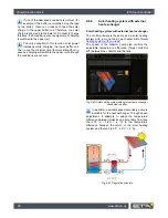
The secondary flow temperature rises when the
collector temperature increases or the speed of

the secondary pump decreases.

Summary of Contents for TWIN 20 kW

Page 1: ...2016 04 02 EN 0000000302 V 001 X 36 0 2303 93412 001 TWIN pellet burner 20 26 kW Operation ...

Page 2: ...ETA Heiztechnik Gewerbepark 1 A 4716 Hofkirchen an der Trattnach Tel 43 0 7734 22 88 0 Fax 43 0 7734 22 88 22 info eta co at www eta co at ...

Page 3: ... outputs 26 9 1 6 Getting started 27 9 1 7 meinETA remote control 32 9 2 Boiler function block log boiler 34 9 2 1 Operating elements 34 9 3 TWIN function block 36 9 3 1 Operating elements 36 9 3 2 Text menu Adjustable parameters 37 9 4 Buffer function block 40 9 4 1 Setting the buffer charging times 41 9 4 2 Buffer with solar heating system 41 9 4 3 Buffer as a combination tank 42 9 4 4 Text menu...

Page 4: ... with 2 internal coils 67 9 8 4 Solar heating system with external heat exchanger 68 9 8 5 Solar heating system with external heat exchanger and stratified charging valve 69 9 8 6 Text menu Adjustable parameters 70 9 9 Pellet store function block 71 9 10 Pellet store with switch unit function block 72 9 10 1 Text menu Adjustable parameters 72 10 Regular cleaning 73 11 Heating value 76 12 Low emiss...

Page 5: ...ment with one of our certified contractors or our own customer service Remote control of the boiler via the internet The remote control enables you to operate your ETA boiler remotely via your own network VNC Viewer or the internet www meinETA at using a PC smartphone or tablet as though you were standing right in front of the ETAtouch control system of your ETA boiler A LAN cable is required for ...

Page 6: ...ts such as from grain waste is not permitted Ensure supply air is free from aggressive substances The air supplied to the boiler must be free from aggressive substances such as chlorine and fluorine from solvents cleaning agents adhesives and propel lants or ammonia from cleaning agents to prevent corrosion of the boiler and chimney Permissible water hardness Water is the intended heat transfer me...

Page 7: ...the system Proper installation The installing contractor is liable for proper installation according to the corresponding installation instructions and the relevant rules and safety regulations If you as customer have installed the heating system partly or entirely without relevant training and in particular without up to date practical experience without having the installation checked by a train...

Page 8: ...urement Buffer and boiler must be cold Before the start of the emission measurement the buffer and the boiler must have cooled down to ensure heat consumption in the heating system during the emission measurement Preferably the boiler should not be used the night before the emission measurement Ensure sufficient heat consumption Open all radiator valves and turn radiator thermostats to maximum 2 1...

Page 9: ...urement 1 The pellet burner must be switched on with the On Off switch In the boiler overview press the Measurement button in order to open the emissions measurement settings window Fig 2 4 Settings window for emission measurement 2 Use the Begin measurement button to enter the date agreed for chimney sweeping The pellet burner will then start in time to reach the permissible operating temperature...

Page 10: ...tdown No doors on the log boiler may be opened during the emission measurement Also do not stoke the fire in the log boiler 5 Switch the boiler back to normal mode after the emission measurement To do this press the Deactivate measurement button in the settings window If you do not press this button the boiler will automatically switch back to normal mode after some time ...

Page 11: ...be cut This protects the sealing edges and enables quiet operation The rotary valve separates the pellet bin from the combustion chamber to prevent back burning in the pellet bin The stoker screw pushes the pellets into the pellet burner s combustion chamber The pellets are burned on the movable rotating grate Automated cleaning takes place during breaks in combustion The grate is rotated against ...

Page 12: ... add wood if the log boiler will immediately take over heating operations WARNING Wood may only be added to the log boiler if it will then be heated up i e take over heating operations Otherwise if the pellet burner is switched on there is a risk that it will switch on when there is a request from the buffer The flames cause the wood to release gas This gas will not be fully combusted and can lead...

Page 13: ... triggering further safety devices such as the safety temperature limiter and the thermal relief valve Heat dissipation is limited by the selected maximum flow temperature in the heating circuits and the target hot water temperature Boiler overheating If a boiler temperature of 90 C is reached the control system switches the draught fan off and a warning message appears on the display Reasons for ...

Page 14: ...eases below 70 C again the safety temperature limiter can be manually released for a restart of the boiler Install safety valve against overpressure A safety valve with 3 bar opening pressure must be installed on the boiler No shut off valve may be installed between the boiler and the safety valve If solar or other heat sources provide energy to the buffer storage tank via a heat exchanger a safet...

Page 15: ...but never in the bottom layer The smaller the pieces the less of them may be added Wood briquettes measuring 6 cm to 10 cm in diameter in compliance with ISO 17225 3 2014 Only 1 oversized split log or 1 stump piece can be placed in the top layer but no more Complete burning may require 2 combustion phases Unsuitable fuel Wet fuel with a moisture content in excess of 20 may not be burned as it resu...

Page 16: ...ore logs every heating cycle If too much wood is loaded an emergency shutdown of the boiler will occur If the boiler overheats the flow of air is stopped The fire will go out but the hot wood will continue to smoulder for a while and the unburned wood gas resulting from the lack of air can create tar deposits in the boiler and flue If this occurs often the boiler s heat exchanger will become clogg...

Page 17: ...all valves completely open to avoid ruining the seals Open valves by turning anti clockwise and then turn back 1 4 turn from the fully open position to relieve pressure on the valve stem Check buffer charging status Before starting the boiler check the current buffer charging status to avoid adding too much wood The table on page 16 shows how much wood should be added The buffer charging status is...

Page 18: ...fuel chamber Use the poker to distribute ashes and charcoal evenly throughout the fuel chamber In the panels the two upper openings for primary air must be free Also the 3 burn through openings in the grate must stay open so that the fire reaches the combustion chamber during ignition Place logs close together in fuel chamber Add the required amount of closely spaced logs to the fuel chamber Stack...

Page 19: ...ndary fuel among the split logs First place half of the required amount of logs in the fuel chamber at least 3 layers Then alternately add the secondary fuel brushwood coarse wood chips round logs wood waste and additional logs The smaller the pieces of secondary fuel are the more logs must be added between them Under no circumstances should secondary fuel brushwood coarse wood chips round logs wo...

Page 20: ...ger pieces of kindling may be needed for ignition CAUTION Never use petrol turpentine or similar materials as an ignition aid risk of explosion The ignition door should be kept open after ignition to monitor the progress of the fire It should only be closed once the boiler s exhaust temperature has reached 100 C How long it takes the fire to start depends on the type of wood used rough spruce may ...

Page 21: ...temperature falls below 80 C the boiler automatically starts the ember burnout Ember burnout status If the Ember burnout button was not pressed the boiler will flush the secondary air ducts with air in order to free them of dust Charcoal and embers remain in the boiler by design so that newly added wood can be ignited more easily Complete ember burnout for cleaning To clean after the final heating...

Page 22: ...g circuit are shown in the control system as function blocks These are listed in the uppermost row on the screen The respective user interface is opened with a single tap of the finger Fig 9 1 ETAtouch control system function blocks 1 Currently selected function block 2 Other function blocks e g hot water tank heating circuit solar heating system 3 Scroll to other function blocks displayed if not ...

Page 23: ...can be found in chapter 9 1 5 Inputs and outputs Any hints errors or faults are displayed in the messages menu see chapter 9 1 4 Messages 9 1 1 User interface The user interface The user interface is always displayed by default If you are in a different view switch to the user view by tapping the symbol upper left and then selecting In the user interface you can set the most important and common s...

Page 24: ...tton Resetting to factory settings is done by pressing the Factory settings button To cancel and close the window tap the arrow on the left side of the screen Only modify parameters whose function you re familiar with Before making any changes read the relevant section of the user manual or configura tion manual or open the integrated help feature If you cannot find sufficient information about a ...

Page 25: ... the screen Fig 9 9 Symbols when an error occurs Types of errors and their meaning Notification A notification does not interrupt operation and therefore no acknowledgement is required Notifi cations inform the user for example that pump anti blocking protection has been activated Warning A warning is displayed on failure of a function which is not absolutely essential for continued operation It c...

Page 26: ...al components of the selected function block are displayed in the inputs and outputs menu e g pumps temperature sensors and mixers When authorization is given the terminal assignment can be changed Also manual mode for e g a pump or a mixer is possible Below is an example of the function block of the heating circuit To view the terminal assignment first select the heating circuit To access the inp...

Page 27: ...configuration menu To close the system settings simply tap the symbol again 9 1 6 2 Setting the language Change the language using the ETAtouch control system The language used can be changed using the ETAtouch control system For this open the system preferences and tap the Language symbol A settings window appears Fig 9 16 Setting the language Select the desired language Following this the ETAtou...

Page 28: ...nge the name tap on the Change name symbol An on screen keyboard appears in order to enter the new name Fig 9 20 On screen keyboard Press the Save button to save To cancel close the window using the arrow on the left side 9 1 6 5 Switch between function blocks The principle of producers and consumers In the user interface the producer of the function block and if present also the consumer s are di...

Page 29: ...cers and consumers vary between the function blocks 9 1 6 6 Setting a time window Setting the charging and operation times In some function blocks the time window for charging the tank for example the buffer and hot water tank or the operating times for example for the heating circuit are set This time window must be created in the settings of the respective function block Subsequently the setting...

Page 30: ...rge time In each field use the arrow keys to set the time and temperature Fig 9 26 Setting time slot and temperature In this example the hot water is charged between 08 00 a m and 8 00 p m to 55 C 2 If an additional time window is necessary add it using the button Adjust as described above A maximum of 3 time windows can be set To delete an unnecessary time window press the button in the selected ...

Page 31: ...ek to copy this is framed and then press the Copy selected day button Fig 9 29 Overview 3 Now select the days of the week for which the time window is to be copied In this example Saturday and Sunday Fig 9 30 Select days of the week Pressing the Mark all days button marks all days 4 Press the Save button to save The overview will be updated accordingly Close the window using the arrow on the left ...

Page 32: ...s the boiler s control system via your home network with a free VNC Viewer To see how remote operation of your boiler works please visit www meinETA at Enter access data for the boiler remote control After receiving your login information after registering on www meinETA at enter it on the control panel in the meinETA Access menu This enables access to remote control of the boiler To enter the log...

Page 33: ... displayed on the platform www meinETA at Establish a meinETA connection Permit or block remote control via the platform www meinETA at If this option is turned off the remote control is also switched off and therefore the boiler is not visible on www meinETA at The symbol of the remote control changes to Full access Thus access is cut off remotely but the control system still remains visible on w...

Page 34: ...lation door stays open for more than 30 minutes an error message appears on the screen If a TWIN burner is connected to the log boiler and the insulation door stays open longer than 1 minute the TWIN burner is switched off by the control system which assumes that the log boiler is being started up Once the fuel is ignited and the exhaust temperature is above 100 C close the ignition door and the i...

Page 35: ... window for emission measurement In addition the locking time of the boiler can be adjusted in the settings window Lock duration button This relates to the set time of the measure ment Within this period a message appears that the boiler is not to be heated up so that the heating system has time to cool The Deactivate measurement button ends the emission measurement and switches the boiler back to...

Page 36: ...he consumer in the overview The minimum operating time of the pellet burner is 30 minutes If there is no heat demand the heating operation is completed upon burnout The operating condition changes to Ember burnout and then back to standby The pellet bin on the boiler is automatically topped up as soon as the stock of pellets falls below a minimum limit The Fill up time button sets the daily time f...

Page 37: ...es for every day of the week Hopper Fill button This fills the reservoir on the boiler immediately independent of the suction time settings 9 3 2 Text menu Adjustable parameters Adjustable parameters Detailed descriptions of the parameters are provided below 9 3 2 1 Start lag Explanation of Start lag This parameter is used to set the length of the delay in operation of the pellet burner after the ...

Page 38: ...dified after consultation with a specialist or ETA customer service The parameters can be found under 9 3 2 4 Empty ash box after Explanation of Empty ash box after This parameter adjusts the quantity of pellets used after which a reminder to empty the ash box is displayed on the screen If the ash box is then only partially full this quantity can be increased If you set the value to zero the remin...

Page 39: ...ETAtouch controller TWIN function block 39 ...

Page 40: ...t has been exceeded in the upper part of the buffer and the adjustable shutdown temperature Buffer bottom off is reached in the lower part The operating mode then changes to Charged If within the loading times there is no heat demand from the consumer the buffer is charged only to the adjustable minimum temperature Buffer top min The consumers connected to the buffer for example heating circuit or...

Page 41: ...r 9 1 6 6 Setting a time window 9 4 2 Buffer with solar heating system Buffer with solar heating system The control principles of the solar heating system and the different variations are described in chapter 9 8 Solar function block In the overview of the buffer the solar heating system appears as another producer for the buffer Fig 9 38 Solar heating system on buffer 1 Currently the buffer is ch...

Page 42: ... 1 Setting the hot water charging times The configurable Switch on diff parameter addition ally allows you to determine how far the hot water temperature can drop before the hot water tank again demands heat from the buffer see 9 4 4 12 Switch on diff Load immediately button This button causes the hot water to be charged to the highest set temperature of all time slots and days of the week if the ...

Page 43: ...e week 3 Add another time window 4 Graphical representation of the time window setting 5 Overview of all time windows for the entire week 6 Delete time window 7 Adjustable hot water temperature within the time window 8 Period of the time window 9 Set back temperature of the hot water outside the time window Setting the time window and copying to other days of the week is described in chapter 9 1 6...

Page 44: ...er value is required if peaks in output have to be covered or very fast heat availability is needed The parameter can be found under 9 4 4 2 Buffer bottom off Explanation of Buffer bottom off This parameter ends charging of the buffer storage tank by the boiler As soon as the Buffer bottom temperature sensor in the buffer storage tank has exceeded the configured Buffer bottom off tempera ture char...

Page 45: ...set the function with the Activate parameter set to Yes this buffer takes up the solar excess This buffer is then charged up to the configured maximum temperature until buffer max The parameter can be found under 9 4 4 5 Priority of the upper and lower sections Explanation of Priority Optional only with solar heating system and buffer with 2 internal coils This parameter sets the priority of the t...

Page 46: ...ler may start beforehand in order to charge the heating circuit or hot water tank During the configured times for solar priority it may happen that the heating circuits or the hot water are not supplied with sufficient heat The parameters for setting the 2 time windows are in Set the start of solar priority before the first time window of the heating circuit and hot water tank Otherwise the boiler...

Page 47: ... 5 C to 8 C if the amount of hot water is insufficient The parameter can be found under 9 4 4 13 Circulation runtime Optional only for combination tank with circulation pump Explanation of Circulation runtime Optional Only with circulation pump This parameter sets the duration for operation of the circulation pump after it has been started This period is only valid inside the set time slot After t...

Page 48: ...48 www eta co at Buffer function block ETAtouch controller The parameter can be found under Hot water tank Circulation Enable circulation ...

Page 49: ...ETAtouch controller Buffer function block 49 ...

Page 50: ...emperature of all time slots and days of the week if the current temperature has dropped below Switch on diff ignoring the current time slot When active the button is highlighted in yellow Mode of operation In the settings menu button the time window for charging the hot water and the desired hot water temperature can be set See chapter 9 5 1 Setting the hot water charging times Within the chargin...

Page 51: ...nly used parameters can be found in the settings Commonly used parameters can be found in the function block settings button There the parameters are identified by the symbol and can be adjusted by tapping This saves you having to search through the text menu for these parameters Adjustable parameters Detailed descriptions of the parameters are provided below 9 5 2 1 Switch on diff Explanation of ...

Page 52: ...veral tanks This parameter sets the priority for solar charging of the hot water tank A high priority means that this tank will be charged by the solar heating system first A low priority means that it will be charged last The parameter can be found under 9 5 2 5 Circulation runtime Explanation of Circulation runtime Optional Only with circulation pump This parameter sets the duration for operatio...

Page 53: ...ETAtouch controller Hot water tank function block 53 ...

Page 54: ...ferent time windows and hot water temperatures can be set See chapter 9 6 1 Setting the hot water charging times Inside these time windows the upper part of the buffer is maintained at no lower than the configured hot water temperature Outside the set time windows the hot water is maintained at the lowest set temperature of the time windows provided that the accumulator tank is sufficiently hot If...

Page 55: ...descriptions of the parameters are provided below 9 6 2 1 Function Automatic venting Explanation of Automatic venting This function attempts to remove introduced air from the fresh water module automatically If the function is activated and the controller detects air intake both pumps are operated at full speed for a short period of time to remove the air from the fresh water module This can also ...

Page 56: ...time Optional Only with circulation pump This parameter sets the duration for operation of the circulation pump after it has been started This period is only valid inside the set time slot After the set period has expired the circulation pump is switched off for the configurable duration of the Circulation pause parameter The parameter can be found under 9 6 2 5 Circulation pause Explanation of Ci...

Page 57: ...ETAtouch controller Fresh water module function block 57 ...

Page 58: ...it is turned on heat is supplied on the basis of the time windows set The temperature is controlled with the heating curve see chapter 9 7 3 The heating curve the optional room sensor and the time window settings see chapter 9 7 2 Setting the heating time slots During a time window the heating circuit is in heating mode If a room sensor is installed this regulates the heating circuit so that the s...

Page 59: ... field is only displayed if a room sensor is installed for the heating circuit The arrows are used to set the required room tempera ture In heating mode an increase of 1 C causes the room temperatures of all time slots for all days of the week to increase by this value In reduced operation mode a reduction by 1 C causes the reduced temperature for all days of the week to decrease correspondingly 9...

Page 60: ...ue outside the time window If the room temperature is set too low there is a danger of freezing 9 7 3 The heating curve Description of the heating curve The heating curve regulates the flow temperature for the heating circuit Each heating circuit has its own heating curve as underfloor heating requires different settings from radiators The heating curve is adjusted in the settings of the heating c...

Page 61: ...determines the maximum flow temperature for the heating circuit to protect it from overheating The factory setting is 45 C for underfloor heating and 65 C for radiators When should the heating curve be adjusted If the rooms are not warming up you should check the following points first before changing the heating curve in the control system Cold rooms are often not only caused by an incorrectly se...

Page 62: ... heating times that are too short are the reason for insufficiently warm rooms Short heating times less than 5 hours continuous heating are particu larly ill advised for underfloor heating because such systems react very slowly Optimal operation is enabled with low feed tem peratures Flow at 10 C and Flow at 10 C for the heating curve and long continuous heating times 10 14 hours Thus the heat is ...

Page 63: ...reduce parameter Flow at 10 C if it is too warm or increase if it is too cold Fig 9 52 Adjust heating curve at outdoor temperatures above freezing At outdoor temperatures below freezing the rooms are always too hot or too cold 1 Only parameter Flow at 10 C is adjusted 2 Change the selector switch to the heating mode position Use the arrow keys to reduce parameter Flow at 10 C if it is too warm or ...

Page 64: ...cordingly the heating circuit will switch on only once the outside temperature falls below 16 C 18 C 2 C The heating limits are adjusted through the settings of the heating circuit button in the heating curve menu button Setting heating limits for heating mode 1 Change the selector switch to the heating mode position Use the arrow keys to reduce parameter Heating threshold so that the heating circ...

Page 65: ... access level is required to perform modifications The parameter can be found under 9 7 4 2 Switch on diff room and Switch off diff room Explanation of Switch on diff room and Switch off diff room Optional only for room sensor These parameters specify the allowed deviation of the set room temperature for switching the heating circuit on and off Example Room temperature setting 21 C Switch on diff ...

Page 66: ... tank Solar heating system with only one tank The solar heating system is controlled by switching the collector pump on and off This is switched on as soon as the collector has exceeded the minimum temperature Collector min and is warmer by the difference Switch on diff factory setting 7 C than the tank being charged Fig 9 57 Solar heating system connected to buffer The speed of the collector pump...

Page 67: ...for buffer with 2 internal coils Switching between two internal coils When switching between two internal coils charging is defined in two different areas of the buffer The purpose is to produce a sufficiently high temperature in the top part of the buffer so that the boiler does not have to start for hot water charging Fig 9 59 Solar heating system with switching between two coils at the buffer T...

Page 68: ...are not met 9 8 4 Solar heating system with external heat exchanger Solar heating system with external heat exchanger The control principle is the same as in a solar heating system with just one tank see chapter 9 8 1 Solar heating system with one tank The speed of the collector pump also controls the adjustable temperature difference Target collector diff between the collector and the tank Fig 9 ...

Page 69: ...that of a buffer with two internal coils The conditions for solar charging into the upper buffer coil are also the same They are described in chapter 9 8 3 Solar heating system for buffer with 2 internal coils The speed control of the secondary pump is identical to that of a solar heating system with an external heat exchanger see chapter Fig 9 61 Regulation principle The only difference is the sw...

Page 70: ...by the solar heating system the temperature of the solar panel Collector is compared with the buffer temperature Buffer bottom Solar If the hot water tank is being charged the Hot water tank bottom temperature is compared A high temperature difference results in a low speed of the solar pump This way a smaller quantity of water is conveyed through the solar panel The water remains in the solar pan...

Page 71: ...let supply 3 Consumer of the pellet store boiler 4 Enter new stock levels after filling Stock level button After filling the pellet store a new supply of pellets is fed in with this button Example 1200 kg of pellets are available and 3000 kg is refilled The new stock will be registered as 4200 kg Entering a minimum level for the pellet stock You can define a minimum level for the pellet stock so t...

Page 72: ...re selecting the locked suction probe it is enabled again symbol Function of the switching unit The conveying and clear modes are represented by a green line between an enabled suction head and the switch unit If a suction head is no longer able to convey pellets the control system automatically switches to clear mode Here the conveying hose now introduces back air in order to dislodge any blockag...

Page 73: ...ollection duct into the ash pan The rear end of the ash collection duct must also be cleared out so that there is no ash in front of the lambda probe head The draught fan runs during de ashing So remove the ash from the boiler slowly and gently to avoid stirring it up too much and having it blown out through the flue Fig 10 1 Removing ash from the combustion chamber Fig 10 2 Removing ash from the ...

Page 74: ...boiler overview window The boiler then performs an ember burnout and switches to Switched off mode On both sides of the ash box is a tension lock that fixes the ash box to the boiler Open both tension locks by pressing the safety catch in the direction of the arrow Fig 10 5 Opening the latches Pull the ash box straight out from the front of the boiler Fig 10 6 Removing the ash box Take off the cov...

Page 75: ... back on the ash box and secure with the tension locks Next connect the ash box to the boiler and secure with the two tension locks at the sides Switch the pellet burner back to automatic mode with the On Off switch in the pellet burner overview ...

Page 76: ...rse a sunny location is preferable but it is more important to find a dry windy place Leave a gap between stacks as well If you stack wood along the wall of a house leave an air gap of at least 10 cm between the wall and the stack of wood Wood stored outside in winter will absorb moisture from precipitation For this reason either move the wood to a covered location in September or at least tempora...

Page 77: ...t logs To avoid any unpleasant surprises when ordering ask how your dealer measures a stere if the price is good you may find 0 85 m acceptable Estimating your wood requirements Each kilowatt of heat output requires 0 9 steres of half metre split beech logs or 1 3 steres of split spruce per year In other words 8 steres of half metre split spruce logs or 5 5 steres of beech will replace 1000 litres...

Page 78: ...ation D06 M10 A0 5 The ash content of the fuel is an indicator for the dust emission According to the current state of science dust emissions from complete combustion are inorganic components in the fuel so called aerosol formers Studies by renowned research institutes have clearly demonstrated that the aerosol formers present in the fuel e g potassium calcium sulphur chlorine sodium zinc silicon ...

Page 79: ...orroding pH value of around 8 pH value between 8 and 9 may require dosing with trisodium phosphate If the heating water s pH value has not itself changed to more than 8 after a week of operation increase it by adding 10 g m of trisodium phosphate Na3PO4 or 25 g m of trisodium phosphate dodecahydrate Na3 PO4 12H2O Wait another 2 4 weeks before making further corrections The pH value must not exceed...

Page 80: ...ue If the system is filled with large amounts of water exactly the same agent must be used again Mixing with other water additives or with antifreeze can result in corrosion 13 2 Refilling Fill up heating water If water refilling in the heating system is required for example to adjust the pressure the same water as used during initial filling should be used wherever possible If only a small amount...

Page 81: ......

Page 82: ...www eta co at ...

Page 83: ......

Page 84: ...www eta co at ...

Reviews: