Page 3
DESCRIPTION
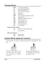
Terminal blocks
BATT
12 Vdc power supply input
AR
Received alarm indicator light
AI
Given alarm indicator light
+12
Output 12 Vdc (max. 100 mA)
AL1
Alarm input 1
AL2
Alarm input 2
COM
Common terminal for inputs IN1 and IN2
IN1
Alarm filter input
IN2
Gong input or auxiliary alarm input
VV2+
Output speaker unit 2
VV2-
Common speaker unit 2
VV1+
Output speaker unit 1
VV1-
Common speaker unit 1
TEL
Local Telephone
Optional PSTN-line board
LTI
PSTN-line or universal gateway input
Ground terminal
Optional relay board
RL1
Relay contact 1
RL2
Relay contact 2
Jumper JP8 for inputs AL1 and AL2
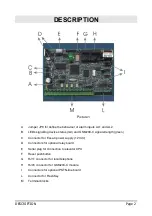
The jumper JP8 (A in picture 1) defines the behaviour of the inputs AL1 and
AL2.
The inputs AL1 and AL2 are at
+12V; the alarm occurs when
they are closed to a – terminal
(e.g. VV2-).
The inputs AL1 and AL2 are at
0V; the alarm occurs when they
are closed to +12V.
Summary of Contents for ST56 INTL
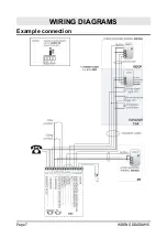
Page 7: ...Page 7 WIRING DIAGRAMS WIRING DIAGRAMS Example connection...
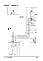
Page 8: ...WIRING DIAGRAMS Page 8 Example connection...
Page 21: ...Page 21 NOTE NOTE...
Page 22: ...NOTE Page 22...
Page 23: ...Page 23 NOTE...


