background image

PLATINOUS SERIES CONTROLLER MANUAL

43

Absolute high/low limits

:

These settings are designed to protect the
chamber against thermal damage.  Set them at
least 10°C higher/lower than the target
temperature.  When tripped, an alarm is
generated and the chamber stops running.

Upper deviation limit

:

This setting is designed to protect specimens
against heat damage.  Basically, it determines the
temperature at which the chamber heater is shut
OFF.  Set it according to the type of specimen
tested.  When tripped, an alarm is generated and
the chamber stops running.  However, when
temperature returns within range, normal control
is restored automatically.

5.4.  Sampling Setup and ON/OFF

1.

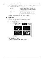
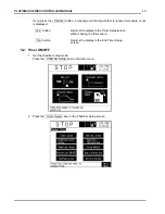
Get the chamber setup mode.
Press the   Chamber Setup  box on the main menu.

TEMP.

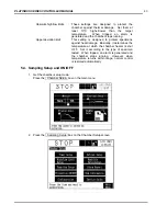
2.

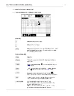
Press the   Sampling Setup  box on the Chamber Setup screen.

Summary of Contents for SCP-220

Page 1: ...SCP 220 CONTROLLER INSTRUCTION MANUAL...

Page 2: ......

Page 3: ...nstant Mode Setup 13 3 1 Constant Mode Setup 13 3 2 Time Signal ON OFF 14 3 3 Product Temp Control Option Detail 15 4 Program Mode Setup 16 4 1 Program Create 16 4 2 Product Temp Control Option Detail...

Page 4: ...tput Setup 56 5 11 6 Name Time Signals 57 5 11 7 Date Screen Saver 58 5 11 8 Register User Password 59 5 11 9 Sensor Offset 59 5 11 10 Buzzer Wick Water Supply 60 5 11 11 Product Temperature Control O...

Page 5: ...injury to the user if the equipment is handled incorrectly CAUTION This mark means dangerous consequences may arise with the possibility of somewhat serious injury to the user and or damage to equipme...

Page 6: ...nual Explains the basics of the Platinous Sterling Series SCP 220 Controller Explains operation from the instrumentation panel in greater detail Quick Reference Reorganizes setting procedures into a s...

Page 7: ...onitor Chamber Time Signal Monitor Program Monitor Chamber Monitor Displayed only in the program mode Constant Mode Setup Constant Setup Time Signal ON OFF Option Edit Delete Copy Program Setup View T...

Page 8: ...T STEP Fig 1 2 Operation Interface 1 3 Screen Layout The instrumentation display is composed of top middle and bottom areas Top Display Area 1 Displays chamber operating status Also pressing this box...

Page 9: ...ters Processing Buttons PREV SCREEN Button Stops processing in course and returns the display to the previous screen If pressed before data changes are entered a message confirming whether to suspend...

Page 10: ...key Enters the displayed input and returns the display to the original screen Keypad Text Input Text can be input in Roman Alphabet or Japanese Kana CLEAR DEL QUIT ENTER keys These keys function in th...

Page 11: ...d in the field boxes If a sensor input error occurs If either dry wet bulb temperature is outside the 0 100 C range for humidity display only When humidity control is OFF However humidity is displayed...

Page 12: ...me scale can be selected between 10 minutes and the Max Rec time set on the Sampling Setup Screen Range Control Expand Increases the displayed scale Reduce Decreases the displayed scale Display Contro...

Page 13: ...er In temperature controlled operations Displays heater output In humidity controlled operations Displays humidifying heater output Refrig Control Indicates refrigerator status Running Stop Time Signa...

Page 14: ...o specimen is cut when the alarm occurs Standard Time Signal 1 2 Indicate whether the user set time signals have been output or not Ext Alarm Indicates whether an alarm is currently active or not Opti...

Page 15: ...PRODUCT below Temp if product control is active For details on air product temp control see section 5 11 11 5 PV Displays the monitored temperature 6 Hum SP Indicates the current target humidity of th...

Page 16: ...and it includes time lost to alarms and time consumed while the chamber is paused 11 End Mode Displays the operating mode the chamber will assume at program end 12 Counter A B Displays repeat range c...

Page 17: ...plains how to make control settings for the constant mode 1 Get the constant setup mode Press the Constant Setup box on the main menu TEMP 2 Input the target temperature humidity Pressing the field bo...

Page 18: ...trol Select between auto and manual OFF 20 50 100 control Normally set to auto control Use only OFF or AUTO 6 Turn the time signals ON OFF as needed Press the m ON box next to Time Signal to make the...

Page 19: ...he product temp set point the air temp set point will change so that it is less than the maximum upper or lower deviation limit 2 Press the number box next to Max or Min deviation to input the deviati...

Page 20: ...umidity and time for each program step The basic procedure is as follows 1 Get the program setup mode Press the Program Setup box on the main menu TEMP 2 Select a program area in which to create a pro...

Page 21: ...n between existing steps Delete Press to delete steps Copy Press to copy existing steps View Displays program data in table form Other Press to name programs select end processing and looping Cancel E...

Page 22: ...p No Boxes 5 The PGM Detail screen will be laid over the display Input the target temperature humidity from there Pressing the field boxes next to Temp SP and Hum SP lays a keypad over the screen to e...

Page 23: ...nly by selecting Yes can ramp control be turned ON However this will turn soak control OFF Humidity ramp control cannot be used if humidity control is OFF Ramp control is automatically kept OFF for st...

Page 24: ...ut pausing 14 Set refrigerator capacity control as needed Select between auto and manual OFF 20 50 100 control To select manual control it is necessary to set the capacity Normal setting is AUTO 15 Tu...

Page 25: ...et point will change so that it is less than the maximum upper or lower deviation limit 2 Press the number box next to Max or Min deviation to input the deviation limit values A keypad will be overlay...

Page 26: ...programs and select end processing 1 Get the Other Setup screen Press the Other box on the bottom of the Program Input Edit screen 2 Name the program you input Pressing the Input box next to PGM Name...

Page 27: ...g determines which program is to be run at the end of the current program It is available only when Start Next Program is selected for the Processing at Program End item Press the Select box next to N...

Page 28: ...he display will return to the Program Input Edit screen Reference Counter Setup Example Counter B Good Counter B Bad Step Counter A Fig 4 1 Counter Setup Example When both counters are used in the pro...

Page 29: ...urns the display to the Program Select Edit screen without saving data updates When the Cancel button is pressed Yes button Discards data updates and returns the display to the Program List screen The...

Page 30: ...every new step added Steps can be added until the End Close button is pressed 4 Set up the new steps as when editing See 4 1 Program Create 4 5 Step Copy This function copies existing steps into othe...

Page 31: ...steps to copy Display the last step to copy with the page scroll keys and press the Step No of that step 4 Select the step where to copy in the selected range Display the destination step with the pag...

Page 32: ...n on the Program Select Edit screen 2 Select the step to delete Display the step to delete with the page scroll keys and press the Step No box of that step 3 A message confirming whether to execute th...

Page 33: ...letes a selected program from the Program List 1 Get a program setup mode Press the Program Setup box on the main menu TEMP 2 Get the program delete mode Press the Delete button on the Program List sc...

Page 34: ...ete command will still be active No button Returns the screen to the Program List screen without deleting the selected program The delete command will still be active 5 If finished deleting programs p...

Page 35: ...ace where a copy in the program Programs cannot be copied into ROM programs Nos 21 30 5 A message confirming whether to execute the operation or not will be displayed Yes button Copies the selected pr...

Page 36: ...d program in table format Selected programs can be viewed but not edited It is a handy feature for checking setup of programs that have been run 1 Get the program setup mode Press the Program Setup bo...

Page 37: ...ng is displayed Temp Target temperature plus if ramp control is OFF or if ON Hum OFF when humidity control is OFF Target humidity plus if ramp control is OFF or if ON Time Exposure time is displayed i...

Page 38: ...PLATINOUS SERIES CONTROLLER MANUAL 34...

Page 39: ...ES CONTROLLER MANUAL 35 5 Chamber Setup 5 1 Timer Setup 5 1 1 Start Timer Setup 1 Get the chamber setup mode Press the Chamber Setup box on the main menu TEMP 2 Press the Timer Setup box on the Chambe...

Page 40: ...on specified days Everyday Starts the chamber everyday Operation Constant Starts the chamber in the constant mode when the timer overflows Mode Program Starts the selected program when the timer over...

Page 41: ...ns the display to the Timer Setup screen without saving the timer setup If you press the Cancel button a message confirming whether to ignore timer setup or not is displayed Yes button Returns the dis...

Page 42: ...PLATINOUS SERIES CONTROLLER MANUAL 38 2 Press the Timer Setup box on the Chamber Setup screen 3 Press the Setup button under the End button...

Page 43: ...in the ON position Mode Stop Stops chamber operation when the timer overflows Day of Week For selecting the days on which to run the timer This setting is available only when Day by Day is selected f...

Page 44: ...or not is displayed Yes button Returns the display to the Timer Setup screen without saving the timer setup No button Returns the display to the End Timer Setup screen 5 2 Timer ON OFF 1 Get the chamb...

Page 45: ...the timer is turned ON At the same time the details of the ON timer s will be displayed in the display area s on the Timer Setup screen 4 After the timer overflows the timer is turned OFF automatical...

Page 46: ...e upper deviation temperature The absolute high low limits will determine the target input range in the constant and program modes 110 C 45 C Fig 5 1 Temperature Alarm Trigger Points and Temperature S...

Page 47: ...is designed to protect specimens against heat damage Basically it determines the temperature at which the chamber heater is shut OFF Set it according to the type of specimen tested When tripped an ala...

Page 48: ...unt of data that can be stored at the Cycle setting at left 4 Turn sampling control ON OFF as needed To clear sampled data press the Clear box ON Resume Starts Resumes trend data sampling OFF Stops tr...

Page 49: ...tons locked by the protection are pressed a warning message is displayed on the screen When an alarm is generated all protections are turned OFF Table 5 3 When Protection is ON Prevent data update Mak...

Page 50: ...Setup Option This option is not available on Platinous Sterling Series Chambers 5 7 Humidity Calculation 1 Get the chamber setup mode Press the Chamber Setup box on the main menu TEMP 2 Press the Hum...

Page 51: ...is also possible to select the method of steam pressure calculation The air Velocity setting is available only when Pernter is selected Dry Bulb Temp Calculates dry bulb temperature from the wet bulb...

Page 52: ...100 assigned to each alarm Type Displays an alarm as Alarm Alarm Displays the name of the alarm When Occurred Displays the date and time when the alarm occurred Display the previous next page respecti...

Page 53: ...TROLLER MANUAL 49 5 9 ROM Information View 1 Get the chamber setup mode Press the Chamber Setup box on the main menu TEMP 2 Press the ROM Information box on the Chamber Setup screen ROM version is dis...

Page 54: ...PLATINOUS SERIES CONTROLLER MANUAL 50 5 10 Service Guide 1 Get the chamber setup mode Press the Chamber Setup box on the main menu TEMP 2 Press the Service Guide box on the chamber Setup screen...

Page 55: ...Tank Filter Cleaning 8 Main Water Tank Cleaning 9 Water Pump Filter Cleaning 10 Humidifying Tray Cleaning 11 Test Area Cleaning 12 Electrical Parts Water Circuit Comp Cleaning 13 Chamber lamp Replacem...

Page 56: ...d has not been registered proceed to step 4 of this procedure 4 The chamber configuration screen will be displayed Select items as needed Chamber Configuration Items 1 Communication Setup 2 Power Reco...

Page 57: ...s manual provided with the PMS CA CG This screen is for setting the chamber address and baud rate used in E BUS communications 1 Select Communication Select on the Chamber Configuration screen and th...

Page 58: ...FF as needed When ON the chamber maintains the current operating state when trouble occurs 4 Turn the door alarm ON OFF as needed Not available on Platinous Sterling Series Chambers ON Pauses the cham...

Page 59: ...ttainment range for the holding time The attainment range will affect the exposure time stating 9program step Also set the attainment range slightly higher lower than deviation limit temperatures resp...

Page 60: ...e Analog Output Setup item Press the 4 box on the chamber Configuration screen 2 Select the output channel to the recorder 3 Select the output signal Process Value Outputs the monitored value of the s...

Page 61: ...unregistered signal is selected a message notifying you to that effect will be displayed 1 Select the Name Time Signals items Press the 5 box on the Chamber Configuration screen 2 Select a time signal...

Page 62: ...month day hour minutes and seconds Table 5 6 Date Setup Input Range Example Year Last 2 digits of western calendar 97 Mnth 1 12 4 Day 1 31 20 Hour 0 23 16 Min 0 59 30 Sec 0 59 45 3 The day of the wee...

Page 63: ...nter key n the keypad Note Do not forget your password 5 11 9 Sensor Offset This screen is for offsetting the temperature humidity input from the sensor in the air conditioner to the built in temperat...

Page 64: ...ter supply mode This setting is for temperature humidity chambers only Always Supplies water at all times Only in Hum Test Supplies water only in humidity tests 4 Set the chamber altitude for humidity...

Page 65: ...SERIES CONTROLLER MANUAL 61 5 Set the No Frost Expand Range This setting should not be changed by the customer Yes Select Yes for all temperature humidity chambers No Select No for all temperature onl...

Page 66: ...e chamber is cooling and another that is used when the chamber is heating There are also tuning parameters that are common to the cooling and heating modes of the testing Pressing any of the numeric b...

Page 67: ...to dampen the affect of the P parameter on the air temp SV The D parameter relates to how quickly the rate of temp change is for the product For more dampening enter a large D value For less dampenin...

Page 68: ...uct temperature control may work slightly better using different numeric values Table 5 8 Product Temperature Control Tuning Parameters Reference Table Change Rate C min P Filter I D 0 1 1 0 36 0 2 0...

Page 69: ...PLATINOUS SERIES CONTROLLER MANUAL 65...

Page 70: ...ctions on Operation Control The Operation Mode Selection screen can be accessed from any screen except in the following cases While confirmation messages are displayed While the keypad is displayed Wh...

Page 71: ...the screen 2 Start operation in the constant mode Press the START button under Constant Mode 3 A message confirming whether to execute the operation or not will be displayed Yes button Starts testing...

Page 72: ...s box on the screen 2 Stop operation in the constant mode Press the STOP button under Stop Operation 3 A message confirming whether to execute the operation or not will be displayed Yes button Stops t...

Page 73: ...ART key on the operating panel or the chamber operating status box on the screen 2 Get the program and start step selection mode Press the PGM No button under PGM Selection 3 Input the No of program t...

Page 74: ...s box on the screen 2 Start the selected program Press the START button under Program Mode 3 A message confirming whether to execute the operation or not will be displayed Yes button Starts the select...

Page 75: ...ing status box on the screen 2 Pause the program Press the PAUSE button under Program Mode 3 A message confirming whether to execute the operation or not will be displayed Yes button Pauses the progra...

Page 76: ...atus box on the screen 2 Restart the program Press the RESTART button under Program Mode 3 A message confirming whether to execute the operation or not will be displayed Yes button Restarts the select...

Page 77: ...l or the chamber operating status box on the screen 2 Jump to the next step Press the NEXT STEP button under Program Mode 3 A message confirming whether to execute the operation or not will be display...

Page 78: ...tatus box on the screen 2 Stop the program Press the STOP button under Stop Operation 3 A message confirming whether to execute the operation or not will be displayed Yes button Stops the selected pro...

Page 79: ...PLATINOUS SERIES CONTROLLER MANUAL 75...

Page 80: ...oller Standard Chamber Instruction Manual Original 1 00 April 30 1999 Edited and Published by ESPEC NORTH AMERICA Revision 1 01 July 25 2001 425 Gordon Industrial Court S W Byron Center MI 49315 Revis...

Reviews: