EsiWelma Srl
URD20SL_en.doc - rev. 0
CO
2
gas detectors – URD20SL
24/09/2010
Gas detection systems for industrial environments
5/8
Mechanical installation
of the optional relay
card
The control card can be expanded with a relay card inserted into a dedicated
connector
CN3
with four SPDT relays that will be activated under the following
conditions: pre-alarm, 1
st
threshold alarm 2
nd
threshold alarm and sensor fail, and
relative LED alerts.
To install the card, follow the instructions below:
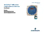
Step 1:
Insert the connection slot provided
with the relay card into the control
card, making sure the flexible tab is
towards the main terminal board.
Find CN3 connector.
CN3 connector
Connection slot
(flexible tab)
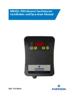
Step 2:
Fit the relay card snugly
and pull the flexible tab
of the connection slot
towards the main
terminal board.
Flexible tab
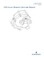
Step 3:
Check the position of the card. Make sure
that all the card pins fit into the CN3
connector and push slightly upwards to
check that the flexible tab on the connection
slot keeps the card in place.
Step 4:
Tick the check box with a
permanent marker to
indicate the presence of
the relay card in the device
IP55
TYPE URD20SL