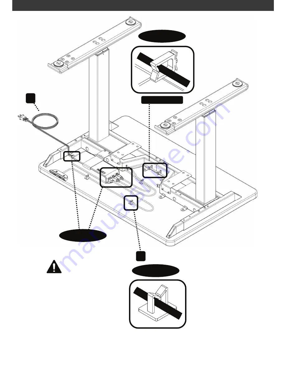
STEP 16-17 – CONTROL BOX WIRES / CABLE MANAGMENT
P15
E
Plug in all Wires to
Control Box (C)
Make Sure All
Connections are
Secure
H
Pre-Installed
STEP 16
STEP 17
Route Wires to Cable Management Clips
Page 1: ...Reuse Recycle MAX Load 265 lbs 120 KG Equally Divided MAX Load 175 lbs 80 KG Per Column CAUTION DO NOT EXCEED MAXIMUM LISTED WEIGHT CAPACITY SERIOUS INJURY OR PROPERTY DAMAGE MAY OCCUR FLEXRISE2 Manua...
Page 2: ...ep at least 80 inches 20 mm free space around the edge of whole frame tabletop Do not operate the system where the temperature is outside the specified limits The frame for desk is not intended to be...
Page 3: ...Frame Column operates irregularly or is tilted Visual observation Perform Resetting The Frame Column stops and can only run downwards Is the frame in highest position When the frame has reached the m...
Page 4: ...em has now been synchronized KY0 version is now ready for use MEMORY SET POSITIONS KY4 only 1 To be performed after Set up Synchronization 2 Move the desk to the desired memory position 3 Press and ho...
Page 5: ...M6 x 10mm Machine Screw M10 x 20mm J K L Wood Screws M5 x 18mm Qty 1 Qty 4 Qty 8 Qty 8 Qty 22 Qty 2 Qty 2 Qty 1 Qty 1 M N P Allen Wrench 4mm O Q Wood Screws M4 x 25mm Machine Screw M6 x 8mm Allen Wren...
Page 6: ...STEP 2 CROSS BAR WIDTH P6 34 in to 64 in 34 in 44 in 44 in 54 in 64 in 64 in 54 in 19 5 in to 23 5 in MAX MAX MIN...
Page 7: ...2 Unscrew Side Leveling Screws with Allen Wrench P to Expand Cross Bar and Tighten once Adjusted to Correct Width STEP 3 STEP 3 Unscrew Bottom Cross Bar Machine Screws and Adjust to Length Unscrew End...
Page 8: ...STEP 4 5 LEG COLUMN P8 B F B N I I O B I I I O I I I Secure with Machine Screws on Cross Bar with Allen Wrench N Secure Leg Column B with Machine Screws I using Allen Wrench O STEP 5 STEP 4...
Page 9: ...EP 6 7 FEET LENGTH 22 in 559 mm 28 in 711 mm O Remove Machine Screws and Secure After Adjusting Length Remove Adjustable Plate for 22 in 559 mm Length STEP 6 STEP 7 STEP 9 STEP 9 Adjust Leveling Pads...
Page 10: ...STEP 8 FEET INSTALLATION P10 A A Q J J B B STEP 8 STEP 8 Secure Feet to Leg Column B...
Page 11: ...STEP 9 ADJUSTABLE FEET PLATE STORAGE P11 STEP 9 Store Extension Plate On Storage Rack STEP 9...
Page 12: ...STEP 10 11 WORK SURFACE ROUTE CABLE K STEP 10 Route Cable Wire Underneath Work Surface STEP 11 Secure Work Surface with Wood Screw K x 20 pcs P12...
Page 13: ...13 OPTION 1 RIGHT SIDE STEP 12 Insert Control Box C to Control Box Bracket G K L G M N K OPTION 1 or OPTION 2 and Secure with Machine Screws M Secure with Wood Screws K x 2 pcs STEP 14 Work Surface C...
Page 14: ...STEP 15 HANDSET P14 D D L L STEP 15 Install Handset D onto Work Surface with Wood Screws L Work Surface Do Not Over Tighten...
Page 15: ...BOX WIRES CABLE MANAGMENT P15 E Plug in all Wires to Control Box C Make Sure All Connections are Secure H Pre Installed STEP 16 STEP 17 STEP 17 Route Wires to Cable Management Clips Route Wires to Cab...
Page 16: ...ESI Ergonomic Solutions NEED HELP PLEASE CONTACT Phone 1 800 833 3746 Email customerservice esiergo com Web www esiergo com...