background image

ESI Dr. 

DAC 

prime


5

HEADPHONE outputs

: there is a 1/4" and a 1/8" TRS connector, allowing you to connect a 

headphone without the use of an adapter. Both headphone outputs send out the same signal. 

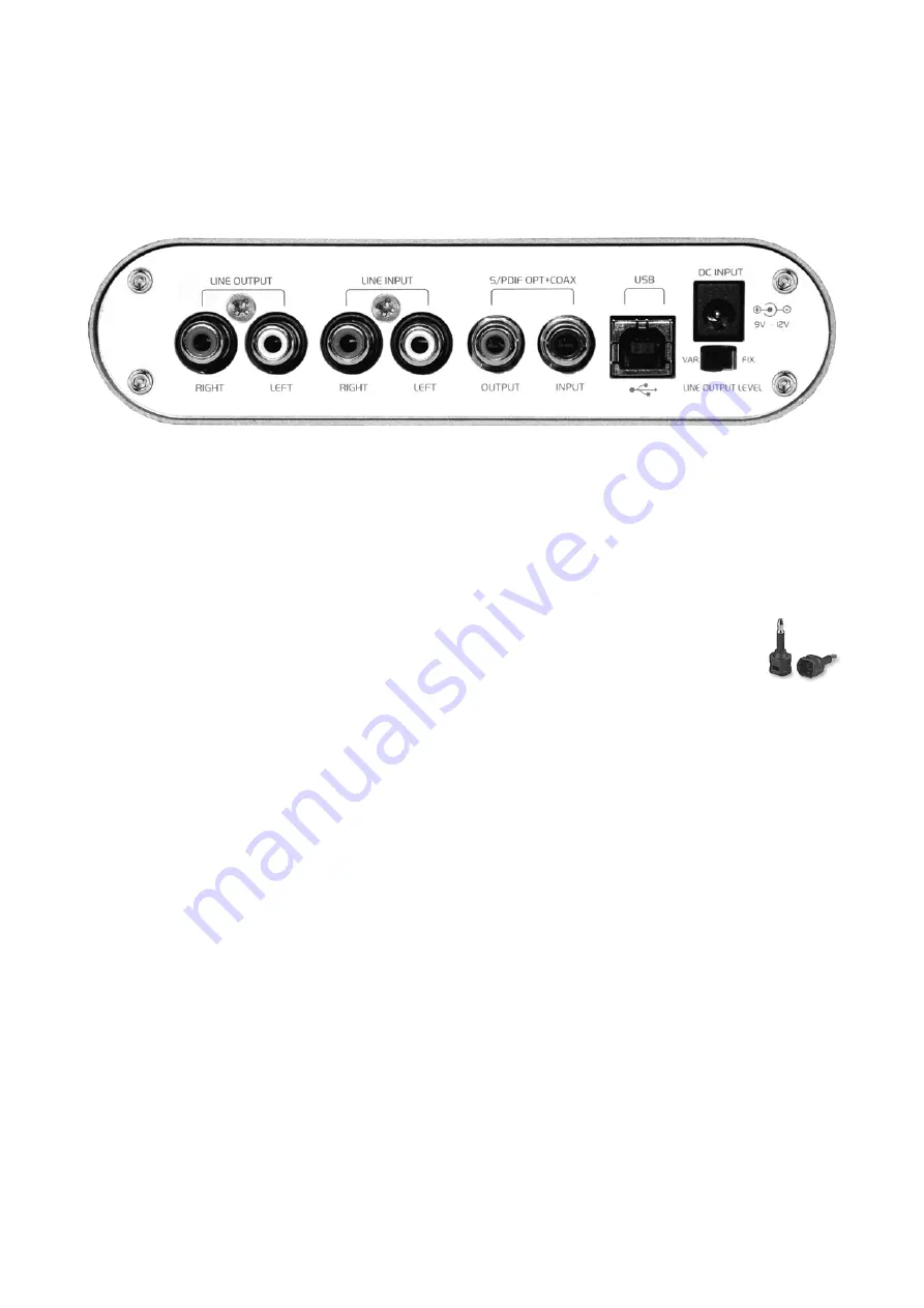
2.2 Rear Panel 


The rear panel provides the following connectors and functions from left to right: 

LINE OUTPUT connectors

: these two RCA connectors are the main analog line level output. For 

example, connect these to your active monitoring speakers or to your amplifier. 

LINE INPUT connectors

: the line input RCA connectors provide a stereo input. You can connect 

any analog source to this input (i.e. a CD player, tape deck, analog mixer, etc.). 

S/PDIF OPT+COAX digital in- and output

: the S/PDIF digital input and outputs are 

both provided as combo connectors supporting RCA connection for coxial signals as 
well as optical signals with miniplug-cables. To connect optical Toslink cables, you 
will need to use one of the (included) Tosling-miniplug adapters. 

USB connector

: the USB connector allows you to connect Dr. DAC prime to your computer with 

the supplied USB cable. 

DC INPUT connector

: this connector is used to connect the included external power supply (see 

section 2.3) with Dr. DAC prime. 

LINE OUTPUT LEVEL switch

: this switch allows you to fix the line output level (

FIX

) or set it to 

variable (

VAR

 – see section 3.2 for more details). 

2.3 Power Supply 

Dr. DAC prime comes bundled with an external power supply (12V and 1.5A). It’s required for 
operation of Dr. DAC prime. Please make sure to connect it to the unit before you start using it. 

3. Operation & Usage 

3.1 Computer Interface 

Dr. DAC prime works both standalone but also as a computer audio interface for recording and 
playback. One of the best features is its simplicity, you can simply plug in the unit with the 
provided USB cable to your Mac or PC. The hardware will automatically be detected and will be 
usable within seconds. 

Summary of Contents for Dr. DAC prime

Page 1: ...High Quality 192kHz DAC with USB Audio Interface User s Guide ...

Page 2: ...ESI Copyright 2009 2011 Revision 3 October 2011 www esi audio com ...

Page 3: ... Driver for Windows Vista and 7 7 3 1 4 Control Panel for Windows 9 3 1 5 Audio Applications 9 3 2 Digital to Analog Converter 10 3 2 1 Fixed Output Level 10 3 2 2 Variable Output Level 10 3 2 3 Mute Function for Line Output 10 3 2 4 192kHz Upsampling 10 3 3 Headphone Amplifier 10 4 Specifications 11 5 General Information 12 5 1 Trademarks 12 5 2 The FCC and CE Regulation Warning 12 5 3 Correspond...

Page 4: ...ith 110dB as well as optical and coaxial S PDIF inputs allowing you to record your own signals with excellent audio quality Dr DAC prime works under Windows XP Windows Vista 7 as well as Mac OS X even without the installation of any driver software that s Plug Play in perfection it could not be more simple 2 Description 2 1 Front Panel The front panel provides the following connectors and function...

Page 5: ...cables To connect optical Toslink cables you will need to use one of the included Tosling miniplug adapters USB connector the USB connector allows you to connect Dr DAC prime to your computer with the supplied USB cable DC INPUT connector this connector is used to connect the included external power supply see section 2 3 with Dr DAC prime LINE OUTPUT LEVEL switch this switch allows you to fix the...

Page 6: ...for Windows XP Disconnect Dr DAC prime before you install the driver if it has been connected already Then launch setup exe from the Windows folder of the included Installation CD or from a download of a recent driver from our website You will now see a dialog as shown on the left picture below Click Next You can define the target directory for the installation now Confirm it with Next The install...

Page 7: ...ed To confirm this please check if the ESI icon is displayed in the taskbar notification area as shown below If yes the driver installation has been completed successfully 3 1 3 Driver for Windows Vista and 7 Disconnect Dr DAC prime before you install the driver if it has been connected already Then launch setup exe from the Windows folder of the included Installation CD or from a download of a re...

Page 8: ...ou will now be prompted to connect the hardware on the next dialog that is shown below on the left Plug in Dr DAC prime Do not click Next yet Instead wait a few seconds for the automatic device driver installation You can monitor this in the task notification area where Windows Vista 7 informs that the driver is installed via a bubble message box You can now finally click OK on the Information dia...

Page 9: ...he analog line input or the digital S PDIF input signal OUTPUT section this section controls the playback volume of the playback signal from your audio applications The pair of mono faders can be controlled together or individually depending on your mouse position perfect for stereo signals The Mute button at the bottom allows you to mute playback A red Mute button indicates that the mute function...

Page 10: ...AC prime i e if you have connected it to active monitoring speakers you should set the LINE OUTPUT LEVEL switch on the back panel to VAR In this case the playback volume for the line output signal is controlled by the VOLUME potentiometer on the front panel 3 2 3 Mute Function for Line Output The MUTE switch on the front panel allows you to mute the playback signal temporarily if set to ON for lin...

Page 11: ...o sample rate converter 32kHz 192kHz input support S PDIF USB input bypass 192kHz upsampling support with SRC4382 1ppm 24 576MHz TCXO for S PDIF input Tenor TE7022L USB audio controller 1ppm 12 000MHz TCXO for USB input to S PDIF I2S output 2 channel line input with RCA connectors line input line output headphone output support AKM AK5386 24bit 192kHz ADC S N ratio 110dB 1pc 8pin DIP opamp S4580P ...

Page 12: ...nsible for compliance could void the user s authority to operate equipment Note This equipment has been tested and found to comply with the limits for a Class A digital device pursuant to Part 15 of the FCC Rules These limits are designed to provide reasonable protection against harmful interference when the equipment is operated in a commercial environment This equipment generates uses and can ra...

Reviews: