background image

2L-7631-00

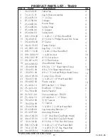
Key #

Part#

Description

Qty.

4A-5522-01
1A-4131-01
2S-6879-10
8S-6758-06
2S-6422-36
2S-6428-06
8S-6606-06
2S-6264-03
WB-1094-00
1B-4049-01
2Q-6084-00
3M-6115-00
4C-0201-00
WB-1110-00
WN-1008-99
WB-1007-99
2N-0214-99 
2W-6269-02
1B-4089-00 
1B-6451-00 
1B-6951-00
3M-4149-00
1B-6477-00
2B-6087-00
2S-4616-14
2S-4615-04
5A-7964-00
2L-7631-00
2S-4616-15
7B-6257-00
7B-6256-99
1B-6475-00
2S-6343-00
2S-4597-08
3M-4156-00
3M-4157-00
1B-4138-00
WB-1075-00
1B-4137-00
3M-8973-04

Table Top
Leg & Brace Assembly
1” U-Clip
Linkage
Name Panel
Safety Strap
U-Support
Safety Latch
1/4-20 x 1 1/2 Hex Head Bolt
#10-24 x ¾ Phillips Round Hd. Screw
2" Caster
Caster Socket
Leg Cap - 1 ½ OD
1/4-20 x 2 Hex Head Bolt
1/4-20 Locknut
#10-24 Locknut
#10 Flat Washer
Wood Bottom Board
#8-32 x 1 ¼” Sheet Metal Screw
#8 x 7/16 Sheet Metal Screw
#8 x 1 7/16 Hex/Phillips Head Screw
Corner Cap - Black
1/4-20 x 3 1/4” Hex Head Bolt
Plastic washer
RH Side Rail -1 ½" Black
End Rail-1 ½” Black
Net & Posts Kit
Owners Manual - T8622
LH Side Rail - 1 ½” Black
5/16" Spacer
¾" Spacer
1/4-20 X 1-1/4 Hex Head Bolt
Leg Mounting Bracket - 1”
Mounting Bracket
11/2” Vinyl End Cap (Right Hand)
11/2” Vinyl End Cap (Left Hand)
#10-24 x ½ Phil. Pan Hd. Screw
1/4-20 x 2 1/4” Hex Head Bolt
1/4-20 X 2 1/2” Hex Head Bolt
Paddle/ball Holder Set

2
4
6
4
2
2
2
2
6
2
4
4
4
4
24
6
2
1
4
100
12
4
4
16
2
2
1
1
2
4
4
4
4
4
2
2
4
4
2
1

1
2
3
4
5
6
7
8
9
10
11
12
13
14
15
16
17
18
19
20
21
22
23
24
25
26
27
28
29
30
31
32
33
34
35
36
37
38
39
40

PRODUCT PARTS LIST - T8620

*PARTS IDENTIFIER ON NEXT PAGE.

17

Summary of Contents for STIGA T8620

Page 1: ... be manufactured and or licensed under the following patents 6120397 5816957 5769744 5119741 4911085 4717157 D460140 D420563 Additional patents may be pending One or more of the listed patents and or pending patents may cover specific product TABLE TENNIS TABLE MODEL NOS T8620 Contact Escalade Sports customer service department at Phone 1 866 873 3528 Toll Free Fax 1 866 873 3533 Toll Free E mail ...

Page 2: ... A An electric screwdriver is helpful in assembly However please set at low torque and use caution because you could overtighten the hardware and strip the screws B Indentation mounting guides are small so look closely when attaching hardware C Table top can be set on top of two saw horses Although this will make assembly easier it is not necessary to complete assembly Always use shipping containe...

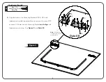
Page 3: ...N YOU ATTEMPT TO OPEN IT TO THE PLAYING POSITION 20 3 IMPORTANT Slot in U Clip End Rail Mounting Indentations Detail A 3 Align the holes in the U clips 3 with Indentations in table top assembly and secure with twelve screws 20 as shown All four holes in each U Clip must align with four Indentations in top See Figure 2 and Detail A Be sure that slot in the three U clips 3 all face the same directio...

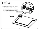
Page 4: ... table top assembly and secure with screws 20 as shown All holes in each Mounting Bracket must align with Indentations in the top See Figure 3 and Detail B Figure 3 Figure 3 Figure 3 4 Hardware Needed Note Indentations in table top are small so look closely 8 x 7 16 Sheet Metal Screw Qty 20 ...

Page 5: ...w 37 and Locknut 16 as shown in Detail C Figure 3 Figure 3 Figure 4 6 Attach Leg Plugs 13 to bottom of the Legs 2 as shown in Figure 4 24 15 16 37 2 Leg Brace 38 33 34 Detail C 5 13 24 Plastic Washer Qty 4 15 1 4 Locknut Qty 2 Hardware Needed 37 10 24 X 1 2 Phillips Pan Head Screw Qty 2 38 10 24 X 1 2 Phillips Locknut Qty 2 16 1 4 20 x 2 1 4 Hex Head Bolt Qty 2 ...

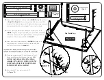
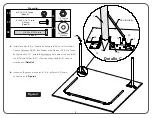
Page 6: ...ut 3 8 inch of screw 19 left sticking out Do not insert screw 19 in middle 3 U Clip See Figure 5 Detail D If you want to see a video on how to insert Screw 19 go to http www escaladesports com customer service videos html Or Scan with your smartphone Note Rotate U Support 7 until you see the screw hole in the slot of U clip 3 Slide U support 7 side to side and front to back if necessary Hardware N...

Page 7: ... Caps onto the ends of the Side Rails 25 29 as shown in Detail E Detail E 11 Lay Corner Caps 22 on table as shown in Figure 6 If Corner Cap sticks above the table top surface of the table flip over so shorter distance is against edge Secure to bottom of table with three Screws 21 See Detail F Detail F Note Rails attach with 20 screws 7 20 Hardware Needed 21 8 x 1 7 16 Sheet Metal Screw Qty 6 8 x 7...

Page 8: ...rews 23 locknuts 15 and plastic spacers 31 Tighten hardware snug enough to keep table stable but do not overtighten Tubes must pivot freely Important Do NOT put other safety strap 6 on this table half It will be installed on second table half later 15 Gently tap caster sockets 12 into U support 7 until flange on sockets touches the edge of the tube DO NOT HIT CASTER SOCKET DIRECTLY WITH A HAMMER S...

Page 9: ...aid of a helper Be sure to place it in a location where it won t be disturbed or damaged If setting on its side be Figure 3 Figure 3 Figure 7B First Table Top 9 AT LEAST TWO ADULTS ARE NEEDED TO MOVE TABLE HALF CAUTION 9 14 1 4 20 x 1 1 2 Bolt Qty 2 24 Plastic Washer Qty 2 15 Locknut Qty 8 Hardware Needed sure to place the bottom edge no less than 12 inches away form the wall Also be sure to place...

Page 10: ...ic washers 24 and hex nuts 15 See Figure 8 NOTE Tighten locknuts 15 finger tight only They will be removed when the two table top halves are connected Figure 3 Figure 3 Figure 8 Second Table Top NOTE Tighten locknuts 15 finger tight only They will be removed when the two table top halves are connected 10 14 24 Plastic Washer Qty 2 15 1 4 Locknut Qty 2 Hardware Needed 1 4 20 x 2 Bolt Qty 2 24 14 15...

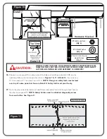
Page 11: ...name panels 5 on first table half with holes in U supports on second table half Secure second table half to top hole in name panel 5 using hex bolt 14 installed earlier and locknuts just removed Secure second table half to bottom hole in name panel 5 with the two hex bolts 9 and locknuts 15 you placed on the floor earlier Tighten locknuts snug but do not overtighten These joints must pivot At this...

Page 12: ...ose a name panel 5 on either side of the table and install one safety latch 8 into the right hand hole on that name panel as shown in Figures 10 11 Detail J Use one screw 10 one washer 17 and one hex nut 16 NOTE Flange on safety latch must extend over top of name panel as shown in Detail K Safety latch must pivot freely 27 Go to the other side of the table and install the second safety latch into ...

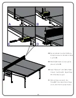
Page 13: ...shown in picture A 29 Slide Paddle Holder onto net post as shown in picture B 30 Insert Slide Lock into Paddle Holder channel See Picture C Repeat Steps 28 30 for other net post 31 Slide net down over posts See Picture D Note Adjust Velcro Straps on one end of net for proper tension 13 ...

Page 14: ...and inward to vertical position Check to be sure that table half is locked in the safety latch 4 Repeat for the other table half OPENING AND CLOSING INSTRUCTIONS READ OPERATING INSTRUCTIONS CAREFULLY BEFORE OPERATING TABLE DO NOT ALLOW CHILDREN TO OPEN TABLE DO NOT CLIMB STAND OR JUMP ON TABLE SERIOUS OR FATAL INJURY MAY RESULT THIS IS NOT A TOY TABLE IS TO BE OPENED OR CLOSED BY ADULTS ONLY FAILU...

Page 15: ...our examination shall disclose to our satisfaction to be thus defective please contact our Warranty Dept 1 866 873 3528 Warranty Dept Or Write us at Escalade Sports Inc P O Box 889 Evansville IN 47706 Attn Warranty Dept Or E mail us at customerservice escaladesports com Other than shipping requirements no charge will be made for such repair or replacement of in warranty Products ESCALADE SPORTS st...

Page 16: ... blister When your table is not in use it should be folded up in a dry area Due to the nature of particle board table top may bow Damp and humid conditions will amplify this This is normal and will not affect playability of table CLEANING YOUR TABLE To clean your table use a soft damp NOT WET cloth only To prevent damage to your table s playing surface DO NOT USE ANY CHEMICALS ABRASIVE OR CLEANING...

Page 17: ...t Leg Cap 1 OD 1 4 20 x 2 Hex Head Bolt 1 4 20 Locknut 10 24 Locknut 10 Flat Washer Wood Bottom Board 8 32 x 1 Sheet Metal Screw 8 x 7 16 Sheet Metal Screw 8 x 1 7 16 Hex Phillips Head Screw Corner Cap Black 1 4 20 x 3 1 4 Hex Head Bolt Plastic washer RH Side Rail 1 Black End Rail 1 Black Net Posts Kit Owners Manual T8622 LH Side Rail 1 Black 5 16 Spacer Spacer 1 4 20 X 1 1 4 Hex Head Bolt Leg Mou...

Page 18: ...24 20 33 20 37 15 16 39 9 30 24 31 15 30 24 6 2 15 23 25 22 21 29 26 1 20 36 35 40 27 2L 7631 00 PARTS LIST ON PREVIOUS PAGE 4 12 11 9 2 9 10 8 14 24 23 31 15 4 13 2 1 7 15 32 18 5 15 16 7 19 19 20 3 3 3 15 15 17 ...

Page 19: ...ajustan antes de lo indicado es posible que los orificios no queden alineados resultando que las partes queden fuera de su lugar y fácilmente no coincidan Deje las tuercas de seguridad levemente flojas hasta que las instrucciones le indiquen ajustarlas 5 Herramientas necesarias Desarmador Phillips una llave de 3 8 y dos llaves de 7 16 Puede utilizar una llave ajustable tambien Guarde estas instruc...

Page 20: ...es necesario para que pueda completar el ensamblado Siempre utilice los cartones del empaque donde venía la mesa para proteger la superficie de la mesa pintada PRECAUCIÓN Asegúrese de que el tablero de la mesa esté seguro sobre los caballetes y NUNCA deje la mesa sola CONSEJOS BREVES Para identificar los tornillos y tuercas Vea la lista de las partes en la página 16 1 Coloque el tablero 1 sobre un...

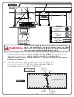
Page 21: ...TÁN MOSTRADAS SI LfAS ABRAZADERAS U ESTÁN COLOCADAS INCORRECTAMENTE USTED LE OCASIONARA DAÑOS IRREPARABLES A SU MESA CUANDO TRATE DE ABRIRLA EN LA POSICIÓN DE JUEGO ADVERTENCIA Si desea ver un vídeo de como poner la abrazadera en U vaya a http www escaladesports com customer service videos html O escanear con su teléfono inteligente Orificios de guía para el riel IMPORTANTE Esté seguro que la ranu...

Page 22: ...os de guía en el tablero e inserte los tornillos 20 como se muestra Todos los orificios en los Soportes 33 y 34 deben de alinearse con los orificios en el tablero Vea la Figura 3 y el Detalle B NOTA Los orificios de guía son muy pequeños ponga atención donde estan los orificios Necesita 8 x 7 16 Tornillo para madera Cant 20 ...

Page 23: ...6 Inserte los Tapones de las patas 13 a las Patas 2 como se muestra en la Figura 4 5 Instale las patas 2 al Soporte de Montaje 34 con el Tornillo de Cabeza Hexagonal 38 dos Rondanas de Plástico 24 y la Tuerca de Seguridad 15 Instale la abrazadera de la pata al soporte 33 con el Tornillo Phillips 37 y Tuerca de Seguridad 16 como se muestra en el Detalle C Abrazadera 1 4 20 x 2 1 4 Tornillo Cant 2 ...

Page 24: ...ra U 3 y dentro del soporte en forma de U 7 Atornillelo al soporte en U hasta que toque el fondo del tubo El tornillo 19 debe sobresalir acerca de de pulgada No inserte el tornillo 19 a la abrazadera de en medio Vea el Detalle D Nota Rote el soporte en forma de U 7 hasta que se vean los orificios a través de las ranuras de las abrazaderas en U 3 donde van los tornillos Si es necesario deslice el s...

Page 25: ...y derecha 35 en el extremo de cada Riel 25 y 29 como se muestra en el Detalle E 10 Alinie los orificios de los rieles con los orificios de guía del tablero atornillelos y asegúrelos con los dieciocho tornillos 20 Vea la Figura 6 y Detalle E 11 Coloque los Protectores de Esquina 22 al tablero como están mostrados en la Figura 6 Si el protector de la esquina sobresale de la superficie del tablero vo...

Page 26: ...xagonal 15 Como se muestra en el Detalle H 12 Una los extremos de los Tubos Conectores 4 con los dos orificios hacia ADENTRO de la pata 2 como están mostrados en el Detalle G y Detalle H Asegurelos con los tornillos 23 los separadores de plástico 31 y las tuercas de seguridad 15 Asegurese que las tuercas y tornillos estén lo suficientemente apretados y seguros para mantener la mesa estable pero no...

Page 27: ...O MENOS SE REQUIERE DE DOS 2 ADULTOS PARA MOVER LA MITAD DE LA MESA Primera Mitad de la mesa 18 15 32 15 24 14 9 9 14 24 15 32 5 15 7 4 7 9 14 1 4 20 x 1 1 2 Tornillo Cant 2 1 4 20 x 2 Tornillo Cant 2 1 4 20 x 1 1 4 Tornillo Cant 4 19 Una la Tabla Inferior 18 a las Placas 5 como se muestra en la Figura 7B Use cuatro tornillos 32 y cuatro tuercas de seguridad 15 20 Prepare una área para el ensambla...

Page 28: ...orma de U 7 a la Segunda mitad de la mesa con los tornillos 14 las rondanas de plástico 24 y las tuercas hexagonal 15 Vea la Figura 8 NOTA Apriete las tuercas de seguridad 15 únicamente con la mano Las quitara cuando los dos lados de las mesas sean unidas NOTA Apriete las tuercas de seguridad 15 únicamente con la mano Las quitara cuando los dos lados de las mesas sean unidas Segunda Mitad de la me...

Page 29: ...15 de los tornillos 14 de la Segunda mitad donde el soporte en U 7 y los Tubos Conectores 4 se unen Alinie los orificios de la Placa 5 de la primera mitad de la mesa con los orificios en los soportes en U 7 de la segunda mitad de la mesa Asegure la segunda mitad de la mesa usando el orificio de arriba de la Placa 5 con los tornillos hexagonal 14 que fueron instalados anteriormente y las tuercas 15...

Page 30: ...tro del lado derecho del orificio sobre la Placa 5 NOTA Los Pasadores de seguridad deben ser instalados diagonalmente de uno al otro Ver la Figura 11 NO SOBRE AJUSTE EL PASADOR DE SEGURIDAD 8 DEBE DE GIRAR LIBREMENTE Figura 10 Figura 11 ADVERTENCIA INSTALE LOS PASADORES DE SEGURIDAD 8 COMO SE MUESTRA ARRIBA PARA EL USO APROPIADO DE LA MESA NO OMITA ESTE PASO NO USE LA MESA HASTA QUE LOS PASADORES ...

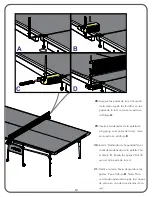
Page 31: ...ping pong en el poste de la red como se muestra en el dibujo B 30 Inserte Deslizador de Seguridad en el canal del sostenedor de la paleta Vea el dibujo C Repita los pasos 28 al 30 para el otro poste de la red 31 Deslice la red a hacia abajo sobre los postes Vea el dibujo D Nota Para una tensión adecuada ajuste las correas de velcro en uno de los extremos de la red A B D C ...

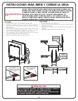
Page 32: ... con el pasador de seguridad 4 Repita los mismos pasos para la otra mitad de la mesa INSTRUCIONES PARA ABRIR Y CERRAR LA MESA LEA AS INSTRUCCIONES DE MANEJO ANTES DE MOVER LA MESA NO PERMITA QUE NIÑOS ABRAN LA MESA NO DEBEN DE PARARSE SUBIRSE O BRINCAR SOBRE LA MESA PUEDEN OCURRIR LESIONES GRAVES O MORTALES ESTA MESA NO ES UN JUGUETE ÚNICAMENTE LOS ADULTOS DEBEN ABRIR O CERRAR LA MESA NO CUMPLIR C...

Page 33: ...o nuestra inspección demuestre que a nuestra satisfacción el mismo realmente es defectuoso sírvase contactar a nuestro Departamento de Garantía 1 866 873 3528 Departamento de Garantía Warranty Dept O escríbanos a Escalade Sports Inc P O Box 889 Evansville IN 47706 Attn Warranty Dept O por correo electrónico a tabletennis escaladesports com Fuera de los gastos de envío no se impondrá cargo alguno p...

Page 34: ...RASIVOS NI PRODUCTOS DE LIMPIEZA sobre el tablero MANTENIMIENTO Lubricar todas las partes movibles incluyendo los puntos de giro Esto garantizará la seguridad y facilidad de uso Guardar en lugar cerrado para impedir daños en la superficie de juego La humedad y los cambios bruscos de temperatura que se producen en patios o áreas similares pueden provocar el alabeo hinchazón fisuras o ampollado de l...

Page 35: ...1 Tubo Conector Placa con logotipo Tira de metal de Seguridad Tubo de Soporte en U Pasador de Seguridad 1 4 20 x 1 1 2 Tornillo de cabeza Hex 10 24 x 3 4 Tornillo Phillips Llanta 2 Casquillo para llanta Tapadera de plástico 1 4 20 x 2 Tornillo de cabeza Hexagonal 1 4 20 Tuerca de Seguridad 10 24 Tuerca de Seguridad 10 Rondana Table Inferior de madera 8 32 x 1 1 4 Tornillo para lamina metal 8 x 7 1...

Page 36: ... EN LA PAGINA ANTERIOR 18 2 34 38 24 20 33 20 37 15 16 39 9 30 24 31 15 30 24 6 2 15 23 25 22 21 29 26 1 20 36 35 40 27 4 12 11 9 2 9 10 8 14 24 23 31 15 4 13 2 1 7 15 32 18 5 15 16 7 19 19 20 3 3 3 15 15 17 2L 7631 00 ...

Reviews: