SECTION 4
MAINTENANCE
PT-19XL PLASMARC CUTTING TORCH
D. Insert the nozzle into the torch.
E. Screw retaining cup onto the torch slowly to
HAND TIGHTNESS. The nozzle will seat
against the gas swirl baffle (P/N 948142). Do
NOT overtighten.
F. Screw heat shield onto nozzle. Do NOT over-
tighten.
4.3 REPLACING ELECTRODE AND GAS
SWIRL BAFFLE
A. Remove heat shield, retaining cup, and nozzle
as described above.
B. Remove electrode by using the 7/16-inch nut
driver (P/N 996568 - supplied with the torch).
If electrode holder did not come out with tip,
then remove it by using removal tool (P/N
999630) supplied with the torch. The lugs will
engage with the slots on the tip holder. Make
sure you hold the nut driver or removal tool
straight, whether removing or reassembling
the electrode, to avoid damaging the gas baffle.
The gas swirl baffle should come out with the
electrode holder. If it does not, remove by
using one finger.
C. Replace electrode if the hafnium insert is pit-
ted more than 0.090 inch.
8
4.1 INTRODUCTION
If this equipment does not operate properly, stop
work immediately and investigate the cause of the
malfunction. Maintenance work must be performed
by an experienced person, and electrical work by a
trained electrician. Do not permit untrained persons
to inspect, clean, or repair this equipment. Use
only recommended replacement parts.
NOTE
For detailed maintenance, troubleshooting, and parts
information on the power source, see Form F-14-483
(PCM-150) and supplement F-15-027 (PCM-1500), or
F-15-528 (PCM-8XL), F-15-108 (ESP-400), or F-15-
109 (ESP-600). F-15-141 (ESP-300). F-15-116 (ESP-
1000).
NOTE
Removing the nozzle from torch to check electrode
wear greatly reduces electrode life. To maximize
electrode life, only remove nozzle when changing
electrode.
4.2 REPLACING PT-19XL NOZZLE
(REFER TO FIGURE 5-1)
A. To remove nozzle, unscrew heat shield and
retaining cup, then grip the nozzle and pull
straight out.
NOTE
Always remove heat shield before removing retaining
cup. If heat shield will not loosen, tighten retaining cup
to reduce pressure on heat shield.
B. Check copper nozzle for melting from exces-
sive current, gouges from internal arcing, or
nicks and deep scratches on the O-ring seal-
ing surface. If any of these defects are visible,
replace the nozzle. (Discoloration of the inter-
nal surfaces and small black starting marks
are normal.) Hafnium particles may be re-
moved with fine sandpaper or steel wool.
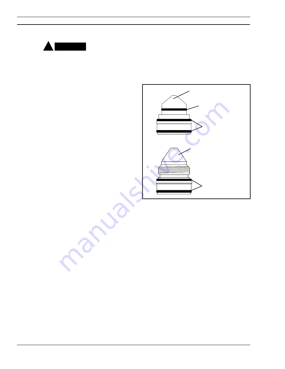
C. Apply a light coating of silicone lubricant (P/N
17672-1 oz. tube) around the periphery of the
nozzle and O-ring. Make sure the O-ring (P/N
181W89) is set evenly around the shoulder of
the nozzle.
!
CAUTION
O-Ring - 994092
(2) O-Ring - 181W89
50 AMP NOZZLE - 34730
(2) O-Ring - 181W89
150 AMP NOZZLE - 21821
250 AMP NOZZLE - 21822
Figure 4-1. Proper O-Ring Position
(50,150 & 250A Nozzles)


