SECTION 2
INSTALLATION
15
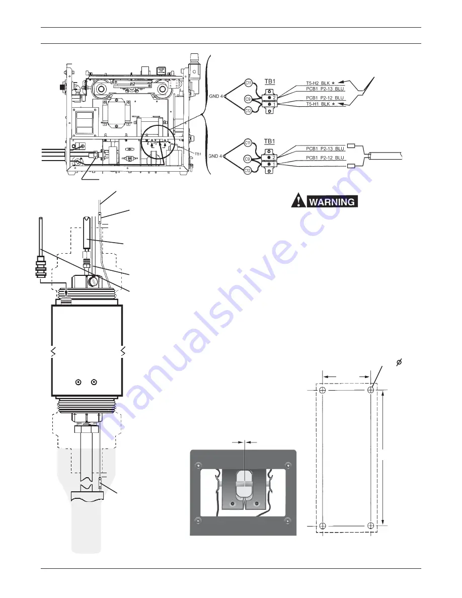
Figure 2.4 Connection Diagram - PCM-875/PT-20AM with Arc Starter
View A-A
“A”
“B”
“C”
“D”
“A”
“B”
“C”
“D”
PILOT ARC CABLE - 37339 (50’)
37340 (100’)
POWER CABLE - 37341 (50’)
37342 (100’)
AIR HOSE - 37343 (50’)
ARC STARTER CABLE - 37410 (50’)
37411 (100’)
SPLICE CONNECTOR*
(Supplied with 37338)
25mm min.
37344 (100’)
Arc Starter
37338
SPLICE CONNECTOR*
(Supplied with 37338)
25mm min.
PT-20AM
TORCH
*Insulate splice connec-
tors with vinyl tubing
and secure with electrical
tape.
SPARK GAP ASSEMBLY
(Torch end of Arc Starter)
.035” (0.9mm)
MOUNTING DIMENSIONS
7”
(178mm)
(4) .250” (6 mm)
Disconnect These
Two Black Leads
Connect Arc Start Cable As Shown. (See step 5 below).
BLK Arc Start
WHT Arc Start
Arc Starter
Cable (Ref.)
ADAPTOR - 999278
2.125”
(54mm)
Make sure all power is off before making following
connections.
1.
Remove cover from PCM-875.
2.
Insert the 4 service lines from Arc Starter through the
torch opening of front panel.
3.
Connect large hole terminal end of Pilot Arc Cable
("A") to connection where shown. Tighten screw
firmly.
4.
Connect adaptor 999278 to fitting where shown.
Connect Air Hose ("C") to adaptor. Connect power
cable ("B") to one of the threaded holes of adaptor.
Tighten all connections firmly.
5.
Locate TB1 Terminal Block. Referring to view D-D
above, disconnect the two black wires from TB1.
Connect the black lead of Arc Starter Cable ("D") to
TB1-1 and the white lead to TB1-2.
6.
Reassemble cover. Proceed to connect the 4 ser-
vice lines to the Arc Starter. Then connect PT-20AM
torch to Arc Starter.
Summary of Contents for PCM-875
Page 29: ...28 D 36587 Figure 5 1 Schematic Diagram PCM 875 208 230 V 50 60 Hz 1 or 3 Phase ...
Page 30: ...29 D 36595 Figure 5 2 Wiring Diagram Sheet 1 of 2 PCM 875 208 230 V 50 60 Hz 1 or 3 Phase ...
Page 31: ...30 Figure 5 3 Wiring Diagram Sheet 2 of 2 PCM 875 208 230 V 50 60 Hz 1 or 3 Phase D 36595 ...
Page 32: ...31 D 36597 B Figure 5 4 Schematic Diagram PCM 875 400 460 V 50 60 Hz 3 Phase 1 2 3 4 5 6 ...
Page 33: ...32 D 36598 Figure 5 5 Wiring Diagram Sheet 1 of 2 PCM 875 400 460 V 50 60 Hz 3 Phase ...
Page 34: ...33 D 36598 Figure 5 6 Wiring Diagram Sheet 2 of 2 PCM 875 400 460 V 50 60 Hz 3 Phase ...
Page 35: ...34 D 36715 A Figure 5 7 Schematic Diagram PCM 875 575 V 60 Hz 3 Phase ...
Page 36: ...35 D 36716 Figure 5 8 Wiring Diagram Sheet 1 of 2 PCM 875 575 V 60 Hz 3 Phase ...
Page 37: ...36 D 36716 Figure 5 9 Wiring Diagram Sheet 2 of 2 PCM 875 575 V 60 Hz 3 Phase ...
Page 47: ...46 ...


