background image

- 7 -

bi21d1ea

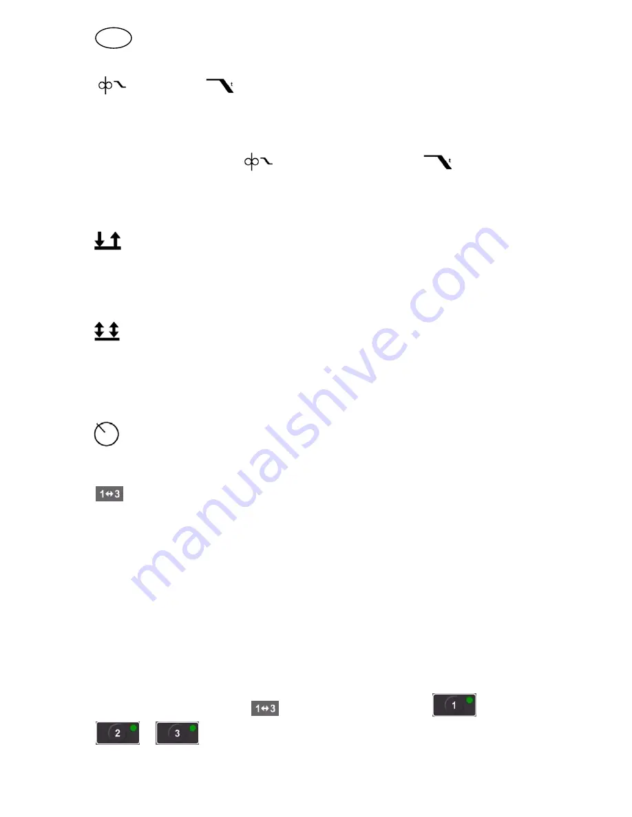
 Crater filling 

 Crater filling time

Crater filling helps to avoid pores, thermal cracking and crater formation in the weld
when welding stops.

When activating crater filling

 also select crater filling time

 using the

setting knob.

This function cannot be used with QSet

.

          2-stroke

With


2-stroke


 gas pre-flow (if used) starts when the welding gun trigger switch is

pressed. The welding process then starts. Releasing the trigger switch stops weld­
ing entirely and starts gas post-flow (if selected).

          4-stroke

With


4 stroke,


the gas pre-flow starts when the welding gun trigger switch is

pressed in and the wire feed starts when it is released. The welding process
continues until the switch is pressed in again, the wire feed then stops and when
the switch is released the gas post-flow starts (if selected).

          Active panel

Settings are made from the control panel.

 Changing welding data

This function permits changing between different welding data memories by a press
on the trigger of the welding gun.

To change without ongoing welding press quickly. If the trigger is held depressed for
too long, the program interprets this as a welding start.

Changing welding data during welding with 2-stroke

During ongoing welding the welding gun's trigger is depressed, to change welding
data memory, release the trigger and depress it quickly.

Changing welding data during welding with 4-stroke

During ongoing welding with 4-stroke the welding gun's trigger is released, to change
welding data memory, depress the trigger and release it quickly.

When activating welding data 

 select welding data memory 

or 

GB

Summary of Contents for Origo MA23

Page 1: ...GB Valid from program version 1 05 0460 454 074 GB 090818 Origot MA23 MA24 Instruction manual ...

Page 2: ...1 Settings 5 2 2 Symbol and function explanation 5 2 3 Hidden MIG MAG functions 8 3 MMA WELDING 10 3 1 Settings 10 3 2 Symbol and Function explanations 10 3 3 Hidden MMA functions 11 4 WELDING DATA MEMORY 12 5 FAULT CODES 12 5 1 List of fault codes 12 5 2 Fault code descriptions 13 6 ORDERING SPARE PARTS 13 WIRE AND GAS DIMENSIONS 14 ORDERING NUMBER 15 ...

Page 3: ... the website www esab com 1 1 Control panel MA23 Setting voltage Setting the wire feed speed current ampere m minute or percent Display Choice of welding method MIG MAG or MMA Choice of 2 stroke or 4 stroke Setting from panel program change with welding gun trigger switch or connecting remote control unit Display of VRD function reduced open circuit voltage is active or inactive Note The VRD funct...

Page 4: ...oke Setting from panel program change with welding gun trigger switch or connecting remote control unit Display of VRD function reduced open circuit voltage is active or inactive Note The VRD function works for power sources where it is implemented Gas flushing Wire inching Indication of which parameter is shown in the display Volts synergy QSet amperes m min seconds or percent Setting the inducta...

Page 5: ...mote control unit OFF or ON x x Gas flushing 2 x x Wire inching x x Inductance 0 100 x x Welding data memory 1 2 3 x x Gas pre flow time 1 0 1 9 9 s x x Unit of measurement 1 0 inch 1 mm x x Burnback time 1 50 250 ms x x Gas post flow time 1 0 1 9 9 s x x 1 These functions are hidden functions see description point 2 3 2 These functions cannot be changed while welding is in progress 2 2 Symbol and...

Page 6: ...g welding parameters Turning the knob clockwise increases the arc length Turning the knob anti clockwise reduces the arc length SHORT ARC When first starting welding with a wire type gas type QSet automatically sets all the necessary welding parameters After that QSet stores all the data to produce a good weld The voltage then automatically conforms to changes in the wire feed speed SPRAY ARC When...

Page 7: ...pressed in again the wire feed then stops and when the switch is released the gas post flow starts if selected Active panel Settings are made from the control panel Changing welding data This function permits changing between different welding data memories by a press on the trigger of the welding gun To change without ongoing welding press quickly If the trigger is held depressed for too long the...

Page 8: ...6 appearing in the display and welding cannot be started whilst the error message is displayed Note The VRD function works for power sources where it is implemented Gas purging Gas purging is used when measuring the gas flow or to flush any air or moisture from the gas hoses before welding starts Gas purging occurs for as long as the button is held depressed and occurs without voltage or wire feed...

Page 9: ...k time is a delay between the time when the wire starts to brake until the time when the power source switches off the welding voltage Too short burnback time results in a long wire stickout after completion of welding with a risk of the wire being caught in the solidifying weld pool Too long a burnback time results in a shorter stickout with increased risk of the arc striking back to the contact ...

Page 10: ...re made from the control panel Remote control unit Settings are made from the remote control unit The remote control unit must be connected to the remote control unit socket on the machine before activation When the remote control unit is activated the panel is inactive VRD Voltage Reducing Device The VRD function ensures that the open circuit voltage does not exceed 35 V when welding is not being...

Page 11: ...patter Drop welding Drop welding can be used when welding with stainless electrodes The function involves alternately striking and extinguishing the arc in order to achieve better control of the supply of heat The electrode needs only to be raised slightly to extinguish the arc Hot start Hot start increases the weld current for an adjustable time at the start of welding thus reducing the risk of p...

Page 12: ...e equipment They are given in the lower part of the display with an E followed by a fault code number A unit number is displayed to indicate which unit has generated the fault Fault code numbers and unit numbers are shown alternately Fault indication indicates that the control panel U 0 has lost contact with the power source If several faults have been detected only the code for the last occurring...

Page 13: ... Check the cables If the fault persists send for a service technician E 18 Lost contact The control panel has lost contact with the power source The current welding process stops Action Check the cables If the fault persists send for a service technician E 27 Out of wire The wire feed unit is not feeding out any wire The current welding process will be stopped and prevents welding start Action Loa...

Page 14: ... 4043 OK Autrod 4043 1 6 100 Ar 5 Al 5356 OK Autrod 5356 1 2 100 Ar 6 Al 5356 OK Autrod 5356 1 6 100 Ar 7 SS OK Autrod 1 0 98 Ar 2 CO2 8 SS OK Autrod 1 2 98 Ar 2 CO2 9 Fe RCW OK Tubrod 1 2 82 Ar 18 CO2 10 Fe RCW OK Tubrod 1 4 82 Ar 18 CO2 11 Fe RCW OK Tubrod 1 6 82 Ar 18 CO2 12 Fe BCW OK Tubrod 1 2 82 Ar 18 CO2 13 Fe MCW OK Tubrod 1 2 82 Ar 18 CO2 14 Fe MCW OK Tubrod 1 4 82 Ar 18 CO2 15 Fe MCW OK ...

Page 15: ...tion manual NL 0460 454 078 Instruction manual ES 0460 454 079 Instruction manual IT 0460 454 080 Instruction manual PT 0460 454 081 Instruction manual GR 0460 454 082 Instruction manual PL 0460 454 083 Instruction manual HU 0460 454 084 Instruction manual CZ 0460 454 085 Instruction manual SK 0460 454 086 Instruction manual RU 0460 454 089 Instruction manual EE 0460 454 090 Instruction manual LV ...

Page 16: ... 31 50 92 22 ESAB international AB Gothenburg Tel 46 31 50 90 00 Fax 46 31 50 93 60 SWITZERLAND ESAB AG Dietikon Tel 41 1 741 25 25 Fax 41 1 740 30 55 North and South America ARGENTINA CONARCO Buenos Aires Tel 54 11 4 753 4039 Fax 54 11 4 753 6313 BRAZIL ESAB S A Contagem MG Tel 55 31 2191 4333 Fax 55 31 2191 4440 CANADA ESAB Group Canada Inc Missisauga Ontario Tel 1 905 670 02 20 Fax 1 905 670 48...

Reviews: